


산업 프로세스에서는 자산과 시설 인프라의 상태를 모니터링하기 위해 여러 데이터 수집 시스템을 사용하는 경우가 많습니다. 이러한 시스템은 독립형 또는 대규모 자동화 Topology 내에서 노드로 구축될 수 있습니다.
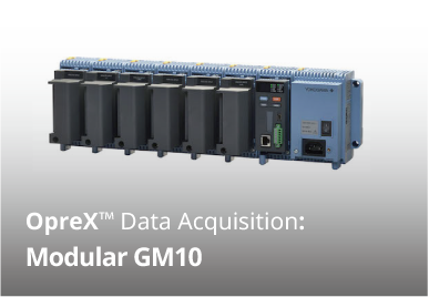
GM10은 확장성이 뛰어난 모듈식 블록 I/O 데이터 수집 시스템 및 데이터 로깅 플랫폼으로, 설치 및 유지보수가 용이하고 프로그래밍이 필요 없으며, 블루투스 연결을 통한 원격 웹 기반 또는 무선 구성 및 모니터링을 지원합니다. 장치는 DIN 레일에 장착하거나 나사에 거는 벽걸이타입, 독립형 데스크톱 어플리케이션으로 설치할 수 있습니다. Yokogawa GM10은 업계 최고의 신뢰성과 측정 정확성을 제공합니다. 또한 광범위한 통신 프로토콜은 네트워크 아키텍처와의 호환성을 보장합니다.
주요 기능
입력/출력의 폭넓은 레인지 사양
10 채널 범용 입력 모듈은 DC 전압, 열전대(TC), RTD, 접점 입력 신호를 측정 합니다. 16 채널 디지털 입력 모듈과 릴레이 출력 모듈도 장착이 가능합니다.
- GX90XA 아날로그 입력 모듈: DC 전압, DC 전류, 열전대(TC), RTD, 접접
- 신제품! GX90XA-10-V1: 고 내전압 AI 모듈: Max. 동상 모드 전압 600V
- GX90XA-04-H0 고속 AI 모듈: DC 전압, DC 전류, 열전대(TC), RTD, 접점
- GX90XA-06-R1 4-Wire RTD 모듈: 4-wire RTD, 4-wire 저항
- GX90YA 아날로그 출력 모듈: 전류 출력 (채널간 절연)
- GX90XD 디지털 입력 모듈: 원격 제어 입력 또는 오퍼레이션 레코딩
- GX90YD 디지털 출력 모듈: 알람 출력
- GX90WD 디지털 입력/출력 모듈: 원격 제어 입력 또는 오퍼레이션 레코딩/알람 출력
- GX90XP 펄스 입력 모듈: 펄스 신호 데이터 수집, 적산
- GX90UT PID 제어 모듈: PID 제어 (2 루프)
PID 제어
- PID 와 프로그램 제어가 가능합니다. (시스템 당 최대 20 루프)
- 인터넷 브라우저를 통해 원격 조작 및 모니터링 가능합니다.
- 셋 포인트 프로그램 제어 기능 (최대 99 패턴)
듀얼 인터벌 측정
- 단일 GM 시스템에 서로 다른 2개의 스캔 인터벌을 설정할 수 있습니다.
확장성
- 시스템 당 최대 420 ch
- Plug & lock 모듈
손쉬운 사용법 *
- 웹 기반의 설정
- 실시간 웹 기반 데이터 감시
모바일 접근성
- 블루투스
- 모바일 어플리케이션
신뢰성
- 안전한 데이터 스토리지
- 고정밀 측정
- 자동 backfill 기능 (GA10 데이터 로깅 소프트웨어)
노이즈 내구성
- Electromagnetic relay 모듈
21 CFR Part 11 지원 (옵션)
- U.S. FDA 21 CFR Part 11 (식품, 제약 제조) 지원.
12 ~ 28 VDC 전원 지원
- 차량용 실차 테스트를 위한 12 ~ 28 VDC 전원 지원
멀티 배치 기능 (옵션)
- 사전 정의된 채널 그룹으로 개별적으로 레코드를 시작/정지 제어하여 데이터 파일을 분리할 수 있습니다.
SLMP 통신 (미츠비시 PLC) (옵션)
- 별도의 시퀀스 프로그램 없이, GP와 미츠비시 PLC가 접속할 수 있도록 해주는 프로토콜 기능 입니다.
OPC-UA 서버 (옵션)
- GP에서 레코딩한 데이터는 호스트 시스템으로 부터 이더넷 통신을 통해 접속할 수 있습니다. (OPC-UA 클라이언트).
우주항공 열처리 지원 heat treatment application AMS2750/NADCAP
- 검교정 보정 스케줄 제어 기능(옵션) 주기적인 검교정 보정에 대한 스케줄 관리를 할 수 있습니다.
OpreX 에 관하여
OpreX는 Yokogawa의 산업 자동화 (IA) 및 제어 비즈니스를 위한 포괄적인 브랜드입니다. OpreX라는 이름은 Yokogawa가 고객과 함께 가치 창출을 통해 개발하는 기술과 솔루션의 우수성을 나타내며 Yokogawa의 IA 제품, 서비스 및 솔루션 전체를 포괄합니다. 이 브랜드는 OpreX Tranformaiton, OpreX Contol, OpreX Measurement, OpreX Execution 및 OpreX Lifecycle의 5가지 카테고리로 구성됩니다. 페이퍼리스 레코더 GP10/GP20은 OpreX Measurement 범주에 속하는 OpreX Data Acquisition 제품 라인업의 일부입니다. OpreX Measurement 범주에는 고정밀 계측, 데이터 수집 및 분석을 위한 현장 장비 및 시스템이 포함됩니다. Yokogawa는 이 브랜드를 통해 고객의 요구 사항을 해결하고 고객의 비즈니스를 변화시키고 성장 시키도록 지원하는 통합 솔루션을 제공 할 것입니다.
Details
스마트한 구조의 차세대 데이터 로거
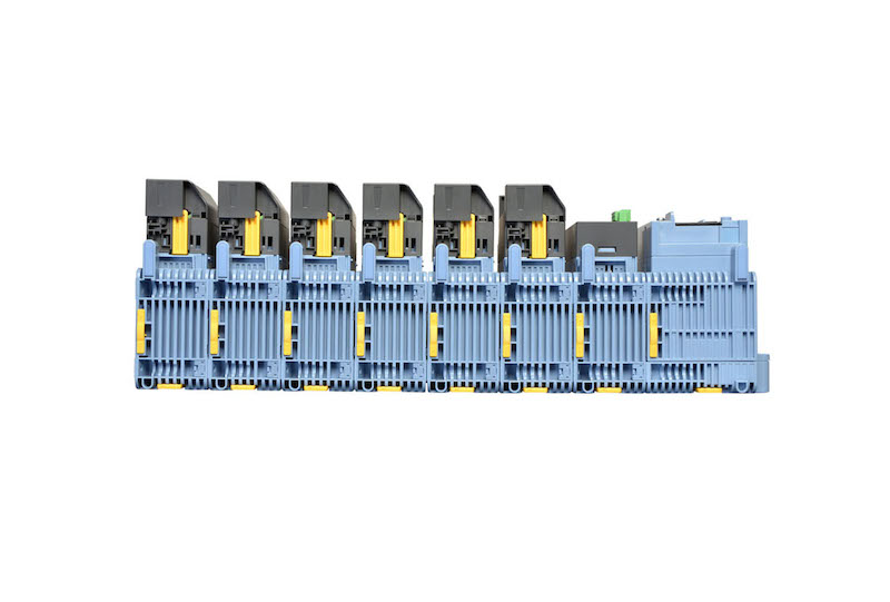
블록식 모듈을 추가하여 채널 증가
YOKOGAWA 전용의 블록식 구조 [특허 기술]
- 한 번에 하나 또는 여러 모듈을 확장
- 링크된 모듈 베이스에 모듈을 내장한 독특한 디자인
- 모듈 베이스는 견고하게 고정 가능(슬라이드 잠금 장치 및 장착 나사도 사용 가능).
- 모듈을 전면 패널에서 삽입 및 탈거하여 유지 관리가 용이

데이터 수집 모듈

최대 100ch의 측정(단일 장치 구성)을 지원하는 표준 구성
최대 10개의 I/O 모듈을 단일 데이터 수집 모듈(GM10)에 연결할 수 있습니다.

다양한 설치 방법

폭 넓은 입력/출력 모듈 라인업
어플리케이션에 따라 모듈을 선택합니다. 내 노이즈, magnetic relay 타입도 사용할 수 있습니다. 모든 모듈에는 쉽게 배선할 수 있도록 탈착식 터미널 블록이 있습니다. SMARTDAC+TM시리즈에 사용되는 것과 동일한 모듈을 사용합니다.

| 모델 | 이름 | 측정/어플리케이션 | 채널 |
|---|---|---|---|
| GX90XA-10-U2 | 아날로그 입력 모듈 | DC 전압, DC 전류 (외장 션트 저항 사용시), 열전대 (TC), RTD, 접점 (solid state relay 스캐너 타입) | 10 |
| GX90XA-10-L1 | DC 전압, DC 전류 (외장 션트 저항 사용시), 열전대 (TC), 접점 (저 내전압 solid state relay 스캐너 타입) | 10 | |
| GX90XA-10-T1 | DC 전압, DC 전류 (외장 션트 저항 사용시), 열전대 (TC), 접점 (electromagnetic relay 스캐너 타입) | 10 | |
| GX90XA-10-C1 | DC 전류 (mA) (solid state relay 스캐너 타입) | 10 | |
| GX90XA-10-V1 | DC 전압, DC 전류 (외장 션트 저항 사용시), 열전대 (TC), 접점 (Solid state relay 스태너 타입) | 10 | |
| GX90XA-04-H0 | DC 전압, DC 전류 (외장 션트 저항 사용시), 열전대 (TC), RTD, 접점 (개별 A/D 타입) | 4 | |
| GX90XA-06-R1 | 4-wire RTD, 4-wire 저항 (solid state relay 스캐너 타입) | 6 | |
| GX90YA | 아날로그 출력 모듈 | 전류 출력 (채널간 절연) | 4 |
| GX90XD | 디지털 입력 모듈 | 원격 제어 입력 또는 동작 레코딩 | 16 |
| GX90YD | 디지털 출력 모듈 | 알람 출력 | 6 |
| GX90WD | 디지털 입력/출력 모듈 | 원격 제어 입력 또는 동작 레코딩/알람 출력 | DI:8/DO:6 |
| GX90XP | 펄스 입력 모듈 | 펄스 신호 데이터 수집, 적산 카운트 | 10 |
| GX90UT | PID 제어 모듈 | PID 제어 (2 루프) | AI:2/AO:2 DI:8/DO:8 |
아날로그 입력 모듈 스캔 인터벌 과 측정 타입
| 타입 | 채널 | 스캔 인터벌 (최소) |
스캐너 | TC | RTD | DCV | DI | mA | 저항 | 기능 |
|---|---|---|---|---|---|---|---|---|---|---|
| 유니버셜 (-U2) | 10 | 100ms | SSR | √ | √ | √ | √ | 유니버셜 | ||
| 저 내전압 Relay (-L1) | 10 | 500ms | SSR | √ | √ | √ | 중저가 | |||
| Electromagnetic Relay (-T1) | 10 | 1s | Relay | √ | √ | √ | 노이즈 내구성 | |||
| DC 전류 입력 (-C1) | 10 | 100ms | SSR | √ | mA 전용 | |||||
| 고 내전압 (-V1) | 10 | 100ms | SSR | √ | √ | √ | 고 내전압 | |||
| 고속 유니버셜 (-H0) | 4 | 1ms | — | √ | √ | √ | √ | 고속 측정 | ||
| 4-wire RTD (-R1) | 6 | 100ms | SSR | √ | √ | 4-wireRTD |
내부 메모리 와 최대 I/O 채널 수
| 타입 | 내부 메모리 | 최대 입력/출력 채널* | |
|---|---|---|---|
| GM10-1 | 500 MB | 단일 구성 | 0 to 100 |
| 멀티 유닛 구성 | 0 to 100 | ||
| GM10-2 | 1.2 GB | 단일 구성 | 0 to 100 |
| 멀티 유닛 구성 | 0 to 420 | ||
고정밀 측정을 지원하는 실제 값
| 입력 타입 | 측정 정확도*1 (typical value*2) | |
|---|---|---|
| DCV | 20 mV | ±(0.01% of reading + 5 μV) |
| 60 mV | ±(0.01 % of reading +5 μV) | |
| 6 V (1-5V) | ±(0.01% of reading + 2 mV) | |
| TC*3 | R, S | ±1.1 °C |
| B | ±1.5 °C | |
| K (-200.0 to 1370.0°C) | ± (0.01% of rdg +0.2°C for 0.0 to 1370.0°C; ± (0.15% of rdg +0.2°C) for -200.0 to 0.0°C | |
| K (-200.0 to 500.0°C) | ± 0.2°C for 0.0 to 500.0°C; ± (0.15% of rdg +0.2°C) for -200.0 to 0.0°C | |
| J | ± 0.2°C for 0.0 to 1100.0°C; ± (0.10% of rdg + 0.2°C) for -200.0 to 0.0°C | |
| T | ± 0.2°C for 0.0 to 400.0°C; ± (0.10% of rdg + 0.2°C) for -200.0 to 0.0°C | |
| N | ± (0.01% of rdg + 0.2°C) for 0.0 to 1300.0°C; ± (0.22% of rdg + 0.2°C) for -200.0 to 0.0°C | |
| RTD | Pt100 (-200.0 to 850.0°C) | ±(0.02% of rdg + 0.2°C ) |
| Pt100 (-150.00 to 150.00°C) | ±(0.02% of rdg + 0.16°C ) | |
최대 420ch (실제 입력 채널)까지 멀티 유닛(멀티 유닛 구성) 확장을 통해 지원
GX90EX 확장 모듈을 통해 최대 420 ch 까지 확장 가능(GM10-2)
GM10-2 대용량 타입에서는 MATH 및 통신 채널을 포함하여 최대 1000ch까지 레코딩 할 수 있습니다. 분산된 설치를 위해 LAN 케이블로 유닛들을 연결합니다.

HUB 나 리피터에 접속하지 않고도 다이렉트 LAN 케이블을 통해 접속이 가능합니다.
* 서브 유닛으로 GX60을 사용할 수 도 있습니다.
분산 설치로 배선을 최소화
레코더 본체가 오프사이트(DUT로 부터 떨어진)에 설치된 경우, 측정 사이트에는 확장 I/O를 설치하게 되면, 각종 센서 나 온도용 열전대(TC) 를 접속하기 위한 긴 배선 작업을 할 필요가 줄어듭니다.

손쉬운 제품 탐색
웹 브라우저에서 간단하게 접속
웹 브라우저를 통해 실시간으로 GM을 모니터링하고 설정을 변경할 수 있습니다. 추가 소프트웨어 없이도 손쉽게 합리적인 비용으로 원활한 원격 모니터링 시스템을 구축할 수 있습니다.
실시간 모니터링
스크롤 바를 움직여 과거 데이터 부터 현재까지의 트랜드를 끊김없이 볼 수 있습니다.

웹 브라우저를 통해 설정 변경
설정은 화면은 아날로그 입력 채널 설정 및 기타 정보를 Excel 로 복사할 수 있도록 해 줍니다. 이를 통해 Excel에서 편리하게 작업한 내용을 다시 복사해 올 수도 있습니다.

트랜드, 디지털, 기타 실시간 디스플레이

데이터 확인 및 GM 설정용 소프트웨어 (무료 다운로드)
유니버셜 뷰어
GM에 저장된 데이터를 열어보거나 인쇄할 수 있습니다. 지정한 구간에 대한 통계 연산을 실행할 수 있으며, ASCII, Excel, 기타 형식으로 변환도 가능합니다.

오프라인 설정 소프트웨어
설정을 저장하고 GM으로 전송할 수 있습니다. 접속은 USB 또는 블루투스를 통해 간단하게 진행됩니다.

폭넓은 사용 온도 범위
동작 온도가 -20°C~60°C인 GM은 설치 환경에 대한 걱정 없이 광범위한 사용 온도 범위를 가지고 있습니다.

테블릿 PC에서도 설정 및 모니터링 가능
블루투스 지원 (/C8 옵션)
현장에 PC가 없어도 태블릿에서 설정을 입력하고 데이터를 모니터링할 수 있습니다. 전용 어플리케이션을 무료로 다운로드할 수 있습니다. 더 많은 정보가 필요하시면 저희 웹사이트를 방문해 주세요.
블루투스를 통한 모니터링
블루투스는 안드로이드 전용 입니다.

Wi-Fi를 통한 모니터링
Wi-Fi 는 안드로이드 iOS 모두 지원 합니다.

강력한 어플리케이션
블루투스 접속
실차 테스트시 간단하게 사용할 수 있습니다.

USB 접속
서비스 요원이 GM의 유지관리를 쉽게 진행할 수 있습니다.

데이터 분석을 쉽고 모바일로
고속 측정 (최소 1 ms)
요꼬가와 전용의 A/D 컨버터가 최소 1ms 까지의 고속 스캔 인터벌을 지원합니다.
- 고속 (1 ms) 측정*
- 전용 A/D 컨버터
* 모듈당 1ch. 2 ms일 경우, 모듈당 2 ch. 5 ms일 경우, 모듈당 4 ch.

| 모델 | 스캔 인터벌 | ||
|---|---|---|---|
| 1ms | 5ms | 10ms | |
| GM10-1 | 1ch | 5ch | 10ch |
| GM10-2 | 5ch | 25ch | 32ch |
듀얼 인터벌 측정
GM의 사용자는 서로 다른 2개의 스캔 인터벌을 설정할 수 있습니다. 이를 통해, 사용자는 하나의 시스템에서도 다양한 타입의 입력에 대하여 유연하게 측정할 수 있는 환경을 제공 받을 수 있습니다. 예를 들어, 고속으로 변화하는 압력과 진동 등과 같은 신호와 상대적으로 느린 온도 신호 등을 동시에 받고 싶을 경우, 듀얼 인터벌을 사용하게 되면 원할하게 측정이 가능합니다. 모듈은 다음의 사진처럼 측정 그룹에서 할당할 수 있습니다.

PID 제어 기능
제어 기능
PID 및 프로그램 제어 활성화
- PID 제어 모듈
모듈 당 2-루프 지원, 1 시스템 당 최대 20 루프 지원 - 셋포인트 프로그램 제어 기능 (/PG 옵션)
최대 99 패턴

원격 조작 및 모니터링
웹 브라우저를 통해 원격으로 조작하고 모니터링이 가능한 어플리케이션 입니다.

MATH (레포트 기능 포함) 기능 과 이벤트 동작
MATH 기능 (/MT 옵션)
기본적인 사직 연산을 포함한 다양한 수학적 연산을 지원합니다(제곱근, 로그, 삼각법). 측정 또는 연산된 데이터를 변수로 활용하여 방정식을 작성하고, 그 결과값으 저장 또는 디스플레이 합니다. 이는 사용자로 하여금 후처리 작업에 대한 공수를 줄여줍니다. 또한 레포트 기능은 시간별, 일별, 월별 레포트를 작성하여 줍니다.

이벤트 동작
레코더로 측정중에 특정 이벤트가 발생하였을 때 실행하는 동작을 할당할 수 있습니다.

우주항공 열처리 AMS2750/NADCAP 지원
검교정 보정 스케줄 제어 기능 (/AH 옵션)
검교정 보정 등과 같은 주기적으로 실행해야 하는 일정 관리. 보정 계수는 본체와 센서에 각각 별도로 설정할 수 있습니다. TUS 레포트 소프트웨어는를 통해 보다 손쉽게 TUS (temperature uniformity survey) 레포트*를 작성하실 수 있습니다.
* TUS 소프트웨어의 자세한 내용은 한국요꼬가와에 문의하여 주시기 바랍니다.

입력 검교정은 아날로그 입력 채널 설정 화면에서 진행하며, 검교정 주기 설정은 스케줄 관리 설정 화면에서 할 수 있습니다.
기기 세트별 별도의 파일로 데이터 레코딩
멀티 배치 기능 (/BT 옵션)
레코더에서 사전 설정한 채널 그룹별로 데이터 파일을 분리하여 각각 독립적으로 시작/정지 제어가 가능합니다. 최대 12개의 독립적인 배치를 생성할 수 있습니다.


레포트 작성 및 네트워크 기능 (/MT 옵션)

다양하고 편리한 네트워킹 기능 제공
Modbus/TCP 와 Modbus/RTU 통신
GM 는 이더넷 통신 환경에서의 Modbus TCP/IP 클라이언트와 서버 모드를 지원 합니다. Modbus RTU 마스터 및 슬레이브는 시리얼 통신 옵션이 필요합니다.
Modbus/TCP (이더넷 커넥션)
Modbus/TCP 와 Modbus/RTU 기능을 이용하면, GM에 서버와 슬레이브 기기의 데이터를 저장할 수 있습니다.*
* 통신 채널 옵션 필요 (/MC 옵션)

(GM10-2에서는 최대 32 개, GP20-1, GM10-1 에서는 최대 16 개의 Modbus/TCP 서버 접속 지원)
(최대 31 개의 Modbus/RTU 슬레이브 접속 가능)
Modbus RTU (RS-422A/485 커넥션)
Modbus/TCP 와 Modbus/RTU 기능을 사용하면, 상위 기기의 데이터를 GM에서 수집할 수 있습니다.

EtherNet/IP 기능 (/E1 옵션)
GM은 EtherNet/IP 서버 기능을 지원합니다. PLC나 다른 기기에서 GM에 접속할 수 있으며, 측정/MATH 채널을 불러오거나 통신 입력 채널에 쓰기*가 가능합니다. (GM10-1: 최대 300 ch, GP20-2: 최대 500 ch).
* 통신 채널 기능 필요 (/MC 옵션)

CC-Link 패밀리 SLMP 통신 기능 (/E4 옵션)
이 프로토콜 기능은 GM에서 미츠비시 전기의 PLC 로 접속이 가능하게 해줍니다. GM을 SLMP 클라언트로 기동하여 GM의 측정 데이터를 PLC에 쓸수 있도록 해주며, PLC의 데이터를 통신 채널*에 쓸수 있도록 해줍니다.
*통신 채널 기능 필요 (/MC 옵션).

요꼬가와 전력 분석기 접속 및 통신 채널 기능 (/E2 and /MC options)
요꼬가와 전력 분석기(WT 시리즈)에서 고도로 정밀하게 측정한 데이터는 GM에서 통신으로 받을 수 있으며, GM 자체 측정 데이터와 함께 기록 및 표시됩니다. 이는 전력 소비량, 온도 및 기타 현상을 동시에 기록할 수 있기 때문에 성능 평가 시험에 매우 이상적입니다.
- 접속 가능한 모델:
Yokogawa Test & Measurement Corp.,
WT 시리즈 전력 분석기,
WT300/WT300E (통신 모드 WT300), WT500, WT1800/WT1800E (통신 모드 WT1800) - 접속 가능한 최대 기기: 16

OPC-UA 서버 (/E3 옵션)
GM에서 획득한 데이터는 호스트 시스템 (OPC-UA 클라이언트)의 이더넷 통신을 통해 액세스할 수 있습니다. 상위 시스템에서 GM 통신 채널로 쓰기 위해서는 통신 채널 기능(/MC 옵션)이 필요합니다.

DARWIN 데이터 어퀴지션 유닛과 호환되는 통신 기능 제공
GM 은 DARWIN 통신 커맨드를 지원합니다. 현재 DARWIN 통신용으로 제작된 프로그램이 GM에서도 동작합니다. 단종된 DARWIN 시리즈를 손쉽게 GM시리즈로 교체 할 수 있습니다.
* 상세 사항은 한국요꼬가와에 문의하시기 바랍니다.

CENTUM/STARDOM 통신 패키지
- CENTUM: LFS2432, DARWIN/DAQSTATION Communication package (for ALE111 [Ethernet])
- STARDOM: NT365AJ DARWIN connection package
FTP 파일 전송
FTP 클라이언트/서버 기능을 사용하면 중앙 집중식 파일 서버에서 데이터를 쉽게 공유하고 관리할 수 있습니다.

E-mail 전송 기능
GM은 알람 알림 보고서, 주기적인 순시 데이터 값, 예약된 보고서, 데이터 및 기타 정보를 포함하는 다양한 정보를 이메일 메시지를 통해 전송할 수 있습니다.

자동 네트워크 셋업 (DHCP) 기능
GM은 DHCP(Dynamic Host Configuration Protocol)를 사용하여 DHCP 서버에서 네트워크 통신에 필요한 설정(IP 주소)을 자동으로 가져올 수 있습니다. 따라서 플랜트 네트워크에 장치를 설치하는 것이 그 어느 때보다 쉬워집니다.

네트워크 시간 서버를 통한 시간 동기화
GM은 클라이언트 모드에서 SNTP 프로토콜을 사용하여 네트워크 시간 서버로 부터 시간 정보를 얻습니다. 이 기능을 통해 시설 내의 모든 GM 기기가 정확하게 시간을 동기화할 수 있습니다. 모든 장치는 조정된 날짜 및 타임스탬프 정보로 데이터를 기록합니다. 또한 GM은 서버 역할을 하여 네트워크의 다른 SNTP 클라이언트 장치에 시간 데이터를 제공할 수 있습니다.

입증된 신뢰성과 높은 안정성
안전한 데이터 저장 능력
측정 및 연산된 데이터는 안전한 내부의 비휘발성 메모리에 지속적으로 저장됩니다. 수동 또는 예약된 간격으로 메모리에 있는 파일이 이동식 미디어에 복사됩니다. 또한 파일을 FTP 서버에 복사하고 보관할 수 있습니다.

| 레코딩 채널 수 | 전체 샘플 시간 |
|---|---|
| 30 | 약 71 일 |
| 100 | 약 23 일 |
| 300 | 약 7 일 |
내부 메모리 1.2 GB 및 레코딩 인버털 1초 일 때
사용자의 어플리케이션에 맞는 파일 형식 선택
보안을 강화하기 위해 측정된 데이터를 바이너리 형식으로 저장할 수 있습니다. 이 형식은 기존 텍스트 편집기나 기타 프로그램에서 해독하거나 수정하기가 매우 어렵습니다. 텍스트 편집기나 스프레드시트 프로그램에서 데이터를 쉽고 직접 열 수 있도록 하려면 텍스트 형식을 선택합니다. 이를 통해 전용 소프트웨어 없이도 측정 데이터를 사용할 수 있습니다.

ASCII 데이터 디스플레이

바이너리 데이터 디스플레이
보안 강화
고객의 데이터를 안전하게 전송하고 수신할 수 있습니다.

SSL: TCP/IP 네트워크를 통해 전송되는 데이터에 대한 암호화 프로토콜
21 CFR Part 11 support (/AS option)
21 CFR Part 11 지원 (/AS 옵션)
Advanced Security 기능 옵션을 통해 GM은 미국 FDA의 Title 21 CFR Part 11 규정을 지원합니다(제약 제조 산업용). 자격 증명 기반 로그인 기능, 전자 서명, 감사 추적, 부당 변경 방지 기능, Active Directory 기반 암호 관리 기능, 로그인 기능 및 기타 보안 기능에 액세스할 수 있습니다.
")
키 잠금
측정 및 연산 동중 시작/정지 조작 오류를 방지하기 위해 GM10의 동작 버튼을 잠글 수 있습니다.

아날로그 프론트 앤드 모듈
Yokogawa 전용의 A/D 컨버터가 고속, 고정밀의 데이터 수집을 가능하게 합니다. (고속 AI, PID 제어 기능)

Standards supported

GX90XA : 아날로그 입력 모듈

사양
| 모델 | GX90XA | |||||||||||||||||||||||||||||||||||||||||||||||||||||||||||||||||||||||||||||||||||||||||||||||||||||||||||||||||||||
|---|---|---|---|---|---|---|---|---|---|---|---|---|---|---|---|---|---|---|---|---|---|---|---|---|---|---|---|---|---|---|---|---|---|---|---|---|---|---|---|---|---|---|---|---|---|---|---|---|---|---|---|---|---|---|---|---|---|---|---|---|---|---|---|---|---|---|---|---|---|---|---|---|---|---|---|---|---|---|---|---|---|---|---|---|---|---|---|---|---|---|---|---|---|---|---|---|---|---|---|---|---|---|---|---|---|---|---|---|---|---|---|---|---|---|---|---|---|---|
| 입력 종류 (채널: 10) |
DC 전압*1, standardized signal*1, 열전대(TC)*1, RTD*2, DI*1, DC 전류 (외장 션트 저항 사용시)*1, DC 전류*3, 저항*4 | |||||||||||||||||||||||||||||||||||||||||||||||||||||||||||||||||||||||||||||||||||||||||||||||||||||||||||||||||||||
| DCV | 20 mV, 60 mV, 200 mV, 1 V, 2 V, 6 V, 20 V, 50 V, 100 V*5 | |||||||||||||||||||||||||||||||||||||||||||||||||||||||||||||||||||||||||||||||||||||||||||||||||||||||||||||||||||||
| Standard signal | 0.4-2 V, 1-5 V | |||||||||||||||||||||||||||||||||||||||||||||||||||||||||||||||||||||||||||||||||||||||||||||||||||||||||||||||||||||
| 저항 | 20, 200, 2000 Ω | |||||||||||||||||||||||||||||||||||||||||||||||||||||||||||||||||||||||||||||||||||||||||||||||||||||||||||||||||||||
| 열전대(TC) | R, S, B, K, E, J, T, N, W, L, U, W97Re3-W75Re25, KpvsAu7Fe, Platinel 2, PR20-40, NiNiMo, W/WRe26, N(AWG14), XK GOST | |||||||||||||||||||||||||||||||||||||||||||||||||||||||||||||||||||||||||||||||||||||||||||||||||||||||||||||||||||||
| RTD | Pt100, JPt100, Cu10 GE, Cu10 L&N, Cu10 WEED, Cu10 BAILEY, Cu10 (20°C) α=0.00392, Cu10 (20°C) α=0.00393, Cu25 (0°C) α=0.00425, Cu53 (0°C) α=0.00426035, Cu100 (0°C) α=0.00425, J263B, Ni100 (SAMA), Ni100 (DIN), Ni120, Pt25, Pt50, Pt200 WEED, Cu10 GOST, Cu50 GOST, Cu100 GOST, Pt46 GOST, Pt100 GOST, PT500*4, PT1000*4 | |||||||||||||||||||||||||||||||||||||||||||||||||||||||||||||||||||||||||||||||||||||||||||||||||||||||||||||||||||||
| DI | Level, Contact | |||||||||||||||||||||||||||||||||||||||||||||||||||||||||||||||||||||||||||||||||||||||||||||||||||||||||||||||||||||
| DC 전류 | 0-20 mA, 4-20 mA | |||||||||||||||||||||||||||||||||||||||||||||||||||||||||||||||||||||||||||||||||||||||||||||||||||||||||||||||||||||
|
스캔 인터벌 |
1/2/5/10/20/50/100/200/500ms, 1/2/5s 타입별 스캔 인터벌
|
|||||||||||||||||||||||||||||||||||||||||||||||||||||||||||||||||||||||||||||||||||||||||||||||||||||||||||||||||||||
| 전원 및 소비 전력 | 본체로 부터 공급, 소비 전력: 2 W 이하 | |||||||||||||||||||||||||||||||||||||||||||||||||||||||||||||||||||||||||||||||||||||||||||||||||||||||||||||||||||||
| 절연 저항 | 입력 회로 와 내부 회로 간 : 20 MΩ이상 (at 500 VDC) | |||||||||||||||||||||||||||||||||||||||||||||||||||||||||||||||||||||||||||||||||||||||||||||||||||||||||||||||||||||
| 내전압 | 입력 회로 와 내부 회로 간 : 1분간 3000 VAC (전류 입력 타입 및 저 내전압 타입: 1분간 1500 VAC, 고 내전압 타입: 1분간 3700 VAC) 아날로그 입력 채널 간: 1분간 1000 VAC (유니버셜 입력 타입의 b 단자 제외) (저 내전압 타입: 1분간 400 VAC, 고속 유니버셜 타입: 1분간 3000 VAC) |
|||||||||||||||||||||||||||||||||||||||||||||||||||||||||||||||||||||||||||||||||||||||||||||||||||||||||||||||||||||
| 터미널 타입 | M3 나사 터미널 또는 클램프 터미널 | |||||||||||||||||||||||||||||||||||||||||||||||||||||||||||||||||||||||||||||||||||||||||||||||||||||||||||||||||||||
| 무게 | 약 0.3 kg | |||||||||||||||||||||||||||||||||||||||||||||||||||||||||||||||||||||||||||||||||||||||||||||||||||||||||||||||||||||
*1 전류 입력 타입에는 설정 불가 (suffix code: -C1) 또는 4-wire RTD/저항 타입 (suffix code: -R1).
*2 전류 입력 타입에는 설정 불가 (suffix code: -C1), electromagnetic relay 타입 (suffix code: -T1), 저 내전압 타입 (suffix code: -L1) 또는 고 내전압 타입 (suffix code: -V1).
*3 전류 입력 타입에만 설정 가능 (suffix code: -C1).
*4 4-wire RTD/저항 타입에만 설정 가능 (suffix code: -R1).
*5 고속 유니버셜 타입에만 설정 가능 (suffix code: -H0).
모델 및 Suffix Code
| 모델 | Suffix Code | 상세 내용 | ||||
|---|---|---|---|---|---|---|
| GX90XA | 아날로그 입력 채널 | |||||
| 채널 수 | -04 | 4 channels (-H0 type only) | ||||
| -06 | 6 channels (-R1 type only) | |||||
| -10 | 10 channels (-C1, -L1, -U2, -T1, -V1) | |||||
| 타입 | -C1 | 전류, 스캐너 타입 (채널간 절연) | ||||
| -L1 | 저 내전압 DCV/TC/DI, 스캐너 타입 (채널간 절연) | |||||
| -U2 | 유니버셜, Solid state relay 스캐너 타입 (3-wire RTD b-terminal common) | |||||
| -T1 | DCV/TC/DI, Electromagnetic relay 스캐너 타입 (채널간 절연) | |||||
| -H0 | 고속 유니버셜, 개별 A/D 타입 (채널간 절연) | |||||
| -R1 | 4-wire RTD/저항, 스캐너 타입 (채널간 절연) | |||||
| -V1 | DCV/TC/DI, 고 내전압 스캐너 타입 (채널간 절연) | |||||
| - | N | Always N | ||||
| 터미널 형태 | -3 | 나사 터미널 (M3) | ||||
| -C | 클램프 터미널 | |||||
| 지역 | N | 일반 | ||||
GX90YA : 아날로그 출력 모듈

사양
| 모델 | GX90YA |
|---|---|
| 출력 타입 (채널: 4) | 전송 출력, 수동 출력 |
| 레인지 | 4–20 mA or 0–20 mA |
| 출력 업데이트 인터벌 | 100 msec (최소) |
| 부하 저항 | 600 Ω 이하 |
| 레졸루션 | 0.002% |
| 전원 및 소비전력 | 본체로 부터 공급, 소비 전력: 3W 이하 |
| 절연 저항 | 출력 회로 와 내부 회로 간: 20 MΩ (at 500 VDC) |
| 출력 채널 터미널 간: 500 VDC, 20 MΩ이상 | |
| 내전압 | 출력 회로 와 내부 회로 간: 1분간 1500 VAC |
| 출력 회로 간: 1분간 500 VAC | |
| 터미널 타입 | M3 나사 터미널 또는 클램프 터미널 |
| 무게 | 약 0.2 kg |
모델 및 Suffix Code
| 모델 | Suffix Code | 상세 내용 | ||||
|---|---|---|---|---|---|---|
| GX90YA | 아날로그 출력 모듈 | |||||
| 채널 수 | -04 | 4 채널 | ||||
| 타입 | -C1 | 전류 출력 (채널간 절연) | ||||
| - | N | Always N | ||||
| 터미널 형태 | -3 | 나사 터미널 (M3) | ||||
| -C | 클램프 터미널 | |||||
| 지역 | N | 일반 | ||||
GX90XD : 디지털 입력 모듈

사양
| 모델 | GX90XD | |
|---|---|---|
| 입력 타입 (채널: 16) |
DI 또는 펄스 입력*1 (Open collector 또는 non-voltage 접점) | |
| ON/OFF 검출 | Open collector: 0.5 V DC의 전압 또는 ON일 경우, 그 이하. 0.5 mA 의 누설 전류 또는 OFF일 경우, 그 이하 Non-voltage 접점: 200 Ω의 저항 또는 ON일 경우, 그 이하. OFF일 경우, 50 kΩ |
|
| 접점 Rating | 12 V DC, 20 mA or more | |
| 전원 및 소비 전력 | 본체로 부터 공급, 소비 전력: 0.7 W 이하 | |
| 절연 저항 | 입력 터미널 과 내부 회로 간: 20 MΩ이상 (at 500 V DC) | |
| 내전압 | 내부 터미널 과 내부 회로 간: 1분간 1500 VAC | |
| 터미널 타입 | M3 나사 터미널 또는 클램프 터미널 | |
| 무게 | 약 0.3 kg | |
펄스 입력 사양*1
| 카운트 시스템 | 펄스의 상승 엣지를 카운트 |
|---|---|
| 최대 펄스 주기 | 250Hz (채터링 필터 : OFF) 125Hz (채터링 필터 : ON) |
| 최소 검출 펄스폭 | Low (close), High (open), 양쪽일 경우 2 ms 이상 |
| 펄스 검출 주기 | 1ms |
| 펄스 측정 정확도 | ± 1 펄스 |
| 펄스 카운트 인터벌 | 측정 인터벌 |
|
필터 |
채터링 필터 On/Off 가능. (채터링 필터가 OFF일 때, GX/GP를 접속할 것. ) |
*1 적산은 math 기능이 필요 (/MT 옵션).
모델 및 Suffix Code
| 모델 | Suffix Code | 상세 내용 | ||||
|---|---|---|---|---|---|---|
| GX90XD | 디지털 입력 모듈 | |||||
| 채널수 | -16 | 16 채널 | ||||
| Type | -11 | Open collector/Non-voltage, 접점 (shared common), Rated 5 VDC | ||||
| - | N | Always N | ||||
| 터미널 형태 | -3 | 나사 터미널 (M3) | ||||
| -C | 클램프 터미널 | |||||
| 지역 | N | 일반 | ||||
GX90YD : 디지털 출력 모듈

사양
| 모델 | GX90YD |
|---|---|
| 출력 타입 (채널: 6) | Relay 접점 (c 접점) |
| Rated 부하 전압 | 100 ~ 240 V AC 또는 5 ~ 24 V DC |
| 최대 부하 전압/전류 | 264 VAC 또는 26.4 VDC, 3A/point (저항 부하) |
| 전원 및 소비 전력 | 본체로 부터 공급, 소비 전력: 1.4 W 이하 |
| 절연 저항 | 출력 터미널 과 내부 회로 간: 20 MΩ (at 500 VDC) |
| 내전압 | 출력 터미널 과 내부 회로 간: 1분간 3000 V AC |
| 터미널 타입 | M3 나사 터미널 |
| 무게 | 약 0.3 kg |
모델 및 Suffix Code
| 모델 | Suffix Code | 상세 내용 | ||||
|---|---|---|---|---|---|---|
| GX90YD | 디지털 출력 모듈 | |||||
| 채널수 | -06 | 6 채널 | ||||
| 타입 | -11 | Relay, SPDT(NO-C-NC) | ||||
| - | N | Always N | ||||
| 터미널 형태 | -3 | 나사 터미널 (M3) | ||||
| 지역 | N | 일반 | ||||
GX90EX : 확장 모듈

모델 및 Suffix Code
| 모델 | Suffix Code | 상세 내용 | ||||
|---|---|---|---|---|---|---|
| GX90EX | I/O 확장 모듈 | |||||
| 포트 | -02 | 2 포트 | ||||
| 타입 | -TP1 | Twisted pair cable | ||||
| - | N | Always N | ||||
| 지역 | -N | 기본 엑세서리 | ||||
GX90WD : 디지털 입력/출력 모듈

사양
| 모델 | GX90WD | |
|---|---|---|
| 입력 타입 (채널: 8) |
DI 또는 펄스 입력*1 (Open collector 또는 non-voltage 접점) | |
| ON/OFF 검출 | Open collector : 0.5 V DC의 전압 또는 ON일 경우 그 이하. 0.5 mA의 누설 전류 또는 OFF 일 경우 그 이하. Non-voltage 접점 : 200 Ω의 저항 또는 ON일 경우 그 이하. OFF 일 경우 50 kΩ |
|
| 접점 입력 Rating | 12 VDC, 20 mA 이상 | |
| 출력 타입 (채널: 6) | Relay 접점 (C 접점) | |
| Rated 부하 전압 | 메인 회로와 접속했을 경우(1차 전원), 150 VAC 이하 메인 회로에서 파생된 회로에 연결된 경우(2차 전원), 250 VAC 이하 (메인 회로가 300 VAC이하 이고, 절연 변압기를 사용) 또는 30 VDC 이하 |
|
| 최대 부하 전류 | 2 A (DC)/2 A (AC), 저항성 부하 | |
| 소비 전력 | 1.9 W 이하 | |
| 절연 저항 | 입력 터미널 과 내부 회로 간: 20 MΩ 이상 (at 500 VDC) 출력 터미널 과 내부 회로 간: 20 MΩ 이상 (at 500 VDC) |
|
| 내전압 | 입력 터미널 과 내부 회로 간: 1분간 1500 VAC 출력 터미널 과 내부 회로 간: 1분간 3000 VAC |
|
| 터미널 타입 | M3 나사 터미널 | |
| 무게 | 약. 0.3 kg | |
각 본체에서 (GM 본체와 확장 I/O), 1 모듈만 사용 가능..
펄스 입력 사양*1
| 카운팅 시스템 | 펄스의 상승 엣지를 카운트 |
|---|---|
| 최대 펄스 주기 | 250Hz (채터링 필터 : OFF) 125Hz (채터링 필터 : ON) |
| 최소 검출 펄스폭 | Low (close), High (open), 양쪽일 경우 2 ms 이상 |
| 펄스 검출 주기 | 1ms |
| 펄스 측정 정확도 | ± 1 펄스 |
| 펄스 카운트 인터벌 | 측정 인터벌 |
|
필터 |
채터링 필터 On/Off 가능. (채터링 필터가 OFF일 때, GX/GP를 접속할 것) |
*1 적산은 math 기능 필요 (/MT 옵션).
모델 및 Suffix Code
| 모델 | Suffix Code | 상세 내용 | ||||
|---|---|---|---|---|---|---|
| GX90WD | 디지털 입력/출력 모듈 | |||||
| 채널수 | -0806 | 8 채널 DIs, 6 채널 DOs | ||||
| 타입 | -01 | Open collector/non-voltage 접점 (shared common), rated 5 VDC; Relay, SPDT, (NO-C-NC) | ||||
| - | N | Always N | ||||
| 터미널 형태 | -3 | 나사 터미널 (M3) | ||||
| 지역 | N | 일반 | ||||
GX90XP : 펄스 입력 모듈

사양
| 모델 | GX90XP |
|---|---|
| 입력 수 | 10 |
| 측정 인터벌 | 100 ms (최소) |
| 입력 타입 | 접점 (open collector, voltage-free 접점), 레벨 (5 V logic) |
| 입력 레인지 | 최대 20 kHz* * 채터링 필터 사용(ON)시 30 Hz |
| 최소 검출 펄스폭 | 25 μs* * 채터링 필터 사용(ON)시 15 ms |
| 측정 정확도 | 카운트 ± 1 펄스 적산중, 이하의 정확도 추가 MATH 시작시: +1 측정 주기 MATH 정지시: -1 측정 주기 * 적산은 math 기능 필요 (/MT 옵션). |
| 채터링 필터 | 최대 5ms 까지 채터링 제거 (각 채널별 on/off 가능) |
| 히스테리시스 폭 | 약 0.2 V |
| 접점, 트랜지스터 Rating | 접점: 15 V DC 이상, 30 mA 이상 Rating. 최소 적용 가능 부하 전류: 1 mA 이하. 트랜지스터: 이하의 Rating: Vce > 15 VDC, Ic > 30 mA |
| 최대 입력 전압 | ±10 V DC |
| 절연 저항 | 입력 터미널 과 내부 회로 간: 20 MΩ 이상 at 500 V DC |
| 내전압 | 입력 터미널 과 내부 회로 간: 1분간 1500 V AC |
모델 및 Suffix Code
| 모델 | Suffix code | 상세 내용 | ||||
|---|---|---|---|---|---|---|
| GX90XP | 펄스 입력 모듈 | |||||
| 채널수 | -10 | 10 채널 | ||||
| 타입 | -11 | DC 전압/open collector/non-voltage 접점 (shared common), rated 5 VDC | ||||
| — | N | Always N | ||||
| 터미널 형태 | -3 | 나사 터미널 (M3) | ||||
| -C | 클램프 터미널 | |||||
| 지역 | N | 일반 | ||||
GX90UT : PID 제어 모듈

사양
| 모델 | GX90UT | |
|---|---|---|
| 제어 루프 | 루프 수 | 2 |
| 아날로그 입력 (측정 채널) | 측정 포인트 | 2 |
| 측정 타입 | DC 전압 (DCV)/standardized signal, TC/RTD, DI (레벨 과 non-voltage 접점)/DC 전류 (외장 션트 저항 사용시) | |
| 스캔 (제어) 인터벌 | 100 ms 또는 200 ms (시스템 글로벌 설정) | |
| 아날로그 출력 (제어 출력/전송 출력/센서 전원) | 출력 채널 | 2 |
| 출력 타입 | 전류 전원, 전압 펄스, 또는 센서 | |
| 전류 출력: 4-20 mA 또는 0-20 mA | ||
| 전압 펄스 출력: ON 전압 = 12 VDC 이상 (부하 저항 600 Ω이상), OFF 전압 = 0.1 VDC 이하 | ||
| 센서 전원으로 사용 가능 (13.0-18.3 VDC) | ||
| 디지털 입력 (스위칭 SP, 동작 모드, etc.) | 입력 채널 | 8 |
| 입력 형식 | Non-voltage 접점, open collector | |
| 접점 Rating: 12 VDC 이상, 20 mA 이상 | ||
| 디지털 출력 (알람, 이벤트, etc.) | 출력 채널 | 8 |
| 출력 형식 | Open collector (sink type) | |
| 출력 접점 용량 | 최대 24 VDC, 50 mA | |
| 내전압/절연 저항 | PID 제어 모듈의 일반 사양서 (GS 04L51B01-31EN) 참조 | |
| 터미널 타입 | M3 나사 터미널 | |
| 무게 | 약 0.3kg | |
모델 및 Suffix Code
| 모델 | Suffix Code | 상세 내용 | ||||
|---|---|---|---|---|---|---|
| GX90UT | PID 제어 모듈 | |||||
| 루프수 | -02 | 2 루프 | ||||
| 타입 | -11 | 8 DIs, 8 DOs | ||||
| — | N | Always N | ||||
| 터미널 형태 | -3 | 나사 터미널 (M3) | ||||
| 지역 | N | 일반 | ||||
-
【Support Information】List of Verified SD Memory Cards (SD Cards)
The SD cards of the following manufacturers have been verified for use with SMARTDAC+ GX/GP/GM, μR10000/μR20000 and FX1000. However, please note that Yokogawa does not guarantee normal operation of the SD card when using with products listed below.
-
【Support Information】List of RoHS
This is a list of recorder and controller products that support the RoHS (2011/65/EU) directive.
-
【Support Information】New Legislative Framework (NLF) Conforming Products
This is a list of recorder and controller products that support the New Legislative Framework (NLF.)
자료실

Improving manufacturing efficiency demands constant action - from uncovering operational waste to identifying areas for continuous improvement. Namely, we must always pursue a cycle of visualizing, analyzing, and solving energy saving challenges.


Controls temperature in, and acquires data from, various internal components of plastic film manufacturing equipment. An easy to use, high cost-performance data acquisition and monitoring system can be assembled by using Ethernet compatible instruments and GA10.


the VZ20X installed near sensors such as temperature, humidity, and vibration, and enables automatic collection of data via the factory LAN. The data collection, monitoring and management can be automatically and regularly monitored with the data logging software GA10. As a result, it contributes to reducing the workload of workers.

Caustic soda and hydrochloric acid, produced in electrolyzer plants, are fundamental materials used in varieties of industries; chemicals, pharmaceuticals, petrol-chemicals, pulp and papers, etc. Profit is the result of the effective production with minimized running / maintenance cost. Proper control of the process brings you stabilized quality of products with the vast operational profit.

Customers want to improve maintenance by predicting failures of existing durable equipment. However, existing equipment do not have enough space, and it is not easy to increase the number of sensors needed to grasp the condition.
To address this issue, the VZ20X’s compact size allows it to be installed between equipment, and data collection can be easily monitored via Ethernet (Modbus/TCP).

AN 04L51B01-02EN

AN 04L51B01-03EN

Customers want to improve maintenance by predicting failures of existing durable equipment. However, existing equipments do not have enough space, and it is not easy to increase the number of sensors needed to grasp the condition.
To address this issue, the VZ20X’s compact size allows it to be installed between equipments, and data collection can be easily monitored via Ethernet (Modbus/TCP).

AN 04L51B01-01EN

The GX20 and GX90UT offer an average value computation function making it ideal for controlling temperature and other fluctuating phenomena. The operating status can be controlled in real time, providing operating cost reductions.

The SMARTDAC+ GM is used extensively for data acquisition in various kinds of conveyance equipment including automobiles, industrial vehicles, in-plant vehicles, ocean shipping vessels, and automated materials handling systems. In addition to being compact and not requiring a PC for data acquisition, the SMARTDAC+ GM can be run under DC power and be operated under harsh conditions (-20° to 60°).

In semiconductor manufacturing processes, a deficient clean room environment can lead to defects and wasted resources, making a strictly controlled clean room indispensable. Maintaining the environment in the clean room requires control of air filters, HVAC systems, room temperature, humidity, airborne particles, and other factors.

Industrial hydrogen fuel cells can be used to produce hydrogen and oxygen from distilled water as well as run in reverse to generate electricity. Fuel cells can also be used in conjunction with intermittent energy sources like solar or wind to provide regulated continuous energy output.

The SMARTDAC+ GM10 is employed by customers who are device manufacturers when they deliver a device to the end user, for on-site monitoring to check that the delivered device is operating stably. If settings are made to the SMARTDAC+ GM10 in the office beforehand, then all that is necessary is to take it to the site and begin data acquisition thus, anyone can conduct on-site data acquisition.

- For remote monitoring (of temperature, pressure, and flow volume), installing the SMARTDAC+ GM in the plant and the SMARTDAC+ GX in the office provides for a scalable, pc-free on-site data monitoring solution.
- You can centralize management of large quantities of data by automatically transferring acquired data to a FTP server.

Data acquired on the SMARTDAC+ GM can be easily monitored through the company network, even from remote locations.

In durability testing of engines, revolutions and load control signals are applied and the results are acquired on a recorder. Using the Data Acquisition System SMARTDAC+ GM's PID control module, you can record data while simultaneously applying control signals.
Downloads
Instruction Manuals
- Data Acquisition System GM Advanced Security Function (/AS) User's Manual (3.9 MB)
- Data Acquisition System GM First Step Guide (8.7 MB)
- SMARTDAC+ STANDARD IP Address Configurator (782 KB)
- Cloud Equipment/Quality Predictive Detection Tool User’s Manual (166 KB)
- Data Acquisition System GM User's Manual (21.7 MB)
- Model GX10/GX20/GP10/GP20/GM10 Multi-batch Function (/BT) User’s Manual (3.5 MB)
- Model GX10/GX20/GP10/GP20/GM10 SLMP Communication (/E4) User's Manual (2.1 MB)
- Model GX10/GX20/GP10/GP20/GM10 WT Communication (/E2) User’s Manual (1.5 MB)
- Model GX10/GX20/GP10/GP20/GM10 EtherNet/IP Communication (/E1) User’s Manual (1.8 MB)
- Model GX10/GX20/GP10/GP20/GM10 Log Scale (/LG) User’s Manual (1011 KB)
- Model GX10/GX20/GP10/GP20/GM10 Communication Command User's Manual (4.0 MB)
- Model GX10/GX20/GP10/GP20/GM10 OPC-UA Server (/E3) User’s Manual (884 KB)
- Model GX10/GX20/GP10/GP20/GM10 Loop Control Function, Program Control Function (/PG Option) User’s Manual (23.6 MB)
- Regarding the Downloading and Installing for the Software, Manuals and Labels/About the Usage of Open Source Software (356 KB)
- Notes on using the Model GX90EX expansion module (I/O expansion module) (177 KB)
- Model GX20/GP20/GM10, UT52A/UT32A, UPM100 920 MHz Wireless Communication, MH920 Console International (For the US and the Korea) (11.6 MB)
- Model 773230 Downloading the Validation Documents (132 KB)
- SMARTDAC+ STANDARD Hardware Configurator User's Manual (4.0 MB)
- Precaution on the use of SMARTDAC+ (597 KB)
- SMARTDAC+ STANDARD Universal Viewer User's Manual (4.1 MB)
- Handling of the SD Memory Card (321 KB)
General Specifications
- Data Acquisition System GM (3.7 MB)
- GX60 I/O Base Unit (Expandable I/O), GX90EX Expansion Module (3.1 MB)
- GX90XA/GX90XD/GX90YD/GX90WD/GX90XP/GX90YA I/O Modules (4.6 MB)
- GX90UT PID Control Module, GX10/GX20/GP10/GP20, GM, Loop Control Function, Program Control function (/PG) (1.8 MB)
- Model 773230 Validation Document for SMARTDAC+ (for the /AS option) (335 KB)
- 415940, 415941 and 415942 Shunt Resistor for Screw Input Terminal (178 KB)
- Equipment/Quality Predictive Detection Tool (340 KB)
- List of RoHS (2011/65/EU) Directive Compliant Products (6-substances RoHS compliant products) (356 KB)
- New Legislative Framework (NLF) Conforming Products (362 KB)
- 438920, 438921 and 438922 Shunt Resistor for Clamp Input Terminal (252 KB)
Software
- Java Runtime for Recorders and Data Loggers *Log-in Required
- SMARTDAC+ PID Control Module Fiemware *Log-in Required
- PLC Communication Protocol Profile (EDS file) for GM10 (For connecting OMRON's PLCs) *Log-in Required
- GM10 Firmware *Log-in Required
- SMARTDAC+ I/O Module Firmware *Log-in Required
- SMARTDAC+ I/O Expansion Module Firmware *Log-in Required
- Offline version: Equipment/Quality Predictive Detection tool OE10 *Log-in Required
- Hardware Configurator *Log-in Required
- IP Address Configurator for GM10 *Log-in Required
- GA10 Data Logging Software *Log-in Required
- Validation Document for SMARTDAC+ *Log-in Required
- GA10 Data Logging Software [60-day free trial] *Log-in Required
- SMARTDAC+ Report Template Builder *Log-in Required
- SMARTDAC+ Excel Report Simulator *Log-in Required
- SMARTDAC+ SettingFileConverter Settings File Conversion Tool *Log-in Required
- EtherNet/IP Profile (EDS file) for GM10 *Log-in Required
- Mobile WEB Application for GX/GP/GM *Log-in Required
- GM Mobile Tool *Log-in Required
- USB Driver for GM10 *Log-in Required
- LabVIEW Driver (for SMARTDAC+ Series) *Log-in Required
- SD Card Formatter *Log-in Required
- Universal Viewer *Log-in Required
Technical Information
- Data Acquisition System Introduction to the Various Features of the GM (2.8 MB)
- Effectively Using SMARTDAC+; Software Introduction (6.1 MB)
- SMARTDAC+ GM Advanced Security Functions White Paper for FDA 21 CFR Part 11 (503 KB)
- Reduce Risk by Eliminating Paper Chart Records (1.6 MB)
- Recorders, Data Loggers, and Control Products Security Standard (488 KB)
- High-speed Measurement Application High-speed Measurement/ Dual Interval Measurement Feature LR Replacement (8.9 MB)
- SMARTDAC+ Loop Control Function, Program Control Function (/PG Option) (9.5 MB)
- SMARTDAC+ Advanced Security Functions White Paper for FDA 21 CFR Part 11 (587 KB)
- DARWIN Replacement Guide (9.1 MB)
Certificates
Drawings
- Analog Input Module GX90XA (531 KB)
- Expandable I/O GX60 (575 KB)
- SMARTDAC+ GM Data Acquisition System (1.8 MB)
- Analog Output Module GX90YA (265 KB)
- Pulse Input Module GX90XP (329 KB)
- Digital Input/Output Module GX90WD (229 KB)
- Digital Output Module GX90YD (267 KB)
- Digital Input Module GX90XD (378 KB)
- Expansion Module GX90EX (207 KB)
동영상

Smart user interface, smart architecture, and smart functionality is achieved in the Yokogawa SMARTDAC+ data acquisition and control product series. SMARTDAC+ consists of the GX and GP touch screen data acquisition stations and the most recent addition – the GM data acquisition and data logging system which is both compact and modular.
기술 및 솔루션, 요꼬가와에 대한 자세한 정보를 찾고 계십니까?
견적 및 기술문의