Introduction
Level transmitter configuration can be very time consuming. Calculations required to determine proper range values for traditional transmitters can become complex due to the physical layout of an application.
DPharp transmitters with advanced software functionality eliminate this time consuming task. With maintenance shops getting smaller, finding equipment that allows us to do more with less becomes a priority.
Application
Using typical smart or conventional products all of the following must be considered:
- The specific gravity (SG) of the process;
- Precise location of 0% and 100%;
- Specific gravity of the capillary fill fluid or sealing liquid (for impulse tubing);
- Vertical height of capillary or impulse piping;
- Exact orientation of the transmitter to the vessel;
- Vertical distance between the flanges.
Depending on the application, the vessel may be open (referencing atmosphere), or closed (under some blanket pressure).
Elevation is typically used when the vessel is closed. To reference blanket pressures, a low side wet leg or remote seal must be used. The low side pressure creates a negative force on the transmitter equal to the vertical height times the specific gravity of the fill fluid.
Suppression is positive pressure created on the high side of the transmitter typically due to a zero point above the transmitter. It is normally employed in an open vessel referencing atmosphere. This is a positive pressure equal to the vertical distance between the 0% point and the transmitter times the specific gravity of the liquid.
Elevation/suppression distance almost never agrees with the piping and instrumentation diagram (P&ID) because actual piping (or remote seal capillaries) do not form exacting angles in the field. In most cases, the precise vertical height is not known until the unit is installed.
Span is the vertical distance of the process times the specific gravity: Figure 1. 10.5 * 0.9 = 9.45 mH2O (31.5 inH2O).
Calibration range is the calculated 0 and 100% taking into consideration positive and negative pressures. In figure 1, the following applies:

Figure 1
0 % = H - L
= ( 4.5 x 0.8 ) - ( 15 x 0.8 )
= 3.6 - 12
= -8.4 mH2O ( -28 inH2O )
100 % = H - L
= ( 4.5 x 0.8 ) + ( 10.5 x 0.9 ) - ( 15 x 0.8 )
= 3.6 + 9.45 - 12
= 1.05 mH2O ( 3.5 inH2O )
The calibration range is: -8.4 to 1.05 mH2O ( -28 to 3.5 inH2O )
Note: SG stands for specific gravity.
The information required to perform the calculation is not readily available. It exists in vendors instruction manuals, P&ID's, but not until the unit is actually installed will all the variables be known because the process piping and capillaries do not form exacting angles in the field.
Solution
DPharp has a smart level setup feature that eliminates the need for elevation/suppression calculations, making set up quick and painless.
Calibration is accomplished by simply following these four steps (for Brain):
- Span the transmitter to the process, height * specific gravity of 0 to 9.45 mH2O (0 to 31.5 inH2O) using the BT200 in C21: LRV and C22: HRV.
- Install to the process using either capillaries or impulse tubing.
- Bring the process to a zero (4mA) condition.
- Through the BT200 execute H10: Auto LRV in the H: AUTO SET menu.
DPharp will calculate the total elevation/suppression and automatically setup the device for that installation. It will even correct the values in software at C21: LRV -28 and C22: HRV 3.5 so the customer can print and record the actual configuration for their maintenance documents.
But what if I cannot bring my process to zero? I have installed the unit, fluid is now in the tank, and the output of the transmitter does not agree with my sight glass. What do I do?
Most transmitters can only make adjustments at 0% or 100%. DPharp can make adjustments anywhere with full elevation or suppression. Once the transmitter is programmed with the correct span, all that is needed is a known point in the process (usually provided by the sight glass.) The output can be adjusted in one of two ways.
- Simply adjust the encoder on the DPharp until the output reaches the known point. In figure 1, the output would be adjusted to 60%.
- The correct value can be entered into J10: Zero Adj. In the case of this example, the proper output value of 60% would be entered. The amount of deviation can be viewed in J11: Zero Dev.
DPharp's digital sensing technology makes this possible. With analog sensing technologies (like capacitance sensors), range changes often necessitate a re-calibration or a trimming of the A/D converter to achieve specified performance. The digital DPharp sensor has no A/D converter, no trimming is necessary. The new range is guaranteed to perform within specification.
Notes
- In level measurement, it is important to maintain a consistent reference pressure. On a closed tank system, this is most efficiently achieved by the use of remote seals and capillary systems.
- It is important to note that the span is to be calculated on process height x specific gravity of the process fluid, and will not necessarily agree with the physical height.
- Output will be linear to the level, regardless of fluid or blanketing system.
- Use of remote seals eliminates problems such as condensation in impulse piping, the requirement for maintenance of condensate pots and fill fluid leaking into the process.
Main Features of DPharp
- ±0.03% Overpressure calibration protection
- ±0.1% per 10years long term stability
- 100:1 turndown
- ±0.055% accuracy
- SIL2 standard
- ±0.1% per 15years long term stability
- 200:1 turndown
- Best-in-class high accuracy, 0.04%
- Multi-sensing output
- Multi-variable transmitter as EJX family line-up
- SIL2 standard
產業別
-
化工
化工廠依靠連續和批量的生產製程,每個生產製程對控制系統都有不同的要求。連續的製程需要一個強大而穩定的控制系統,該系統不能因為自身失效而導致生產線關閉;批量製程的重點在於擁有一個可以靈活調整地公式和程序的控制系統。兩種系統都需要在產品質量記錄中進行管理,並且能夠執行非常規操作。橫河電機憑借廣泛的產品組合、經驗豐富的系統工程師、遍及全球的銷售和服務網絡,為每個工廠流程提供解決方案。
-
水和廢水
橫河電機通製開發更節能的技術,幫助減少運營的碳排放,以及構建保護環境免受污染的堅固建築,為可持續水生產提供控制解決方案。橫河憑借先進的技術和廣泛的應用專業知識與客戶合作,提供可持續水生產的解決方案,促進客戶的業務,並讓整個工廠在生命周期中增加價值。橫河的技術和產品可提高工廠的性能,確保它們在當今的水處理領域中具有競爭力,並降低運營成本。橫河支持市政和工業水處理領域的各種水控制方面的應用。
-
電力
電力
-
石油和天然氣
石油和天然氣
-
石油和天然氣下游
近年來,石油和天然氣下游產業面臨著越來越多的挑戰。這些挑戰包括待加工原料的特性變化、工業設施及設備的老化、能源成本的上升、缺乏能夠使煉油廠安全有效運行的熟練技術工人,以及市場和客戶的需求不斷變化。
多年來,橫河與許多下游公司合作,致力於提供應對這些挑戰和問題的工業解決方案。橫河的解決方案幫助工廠投資者盡可能實現最大的盈利能力和工廠內可持續的安全。 -
鋼鐵
在鋼鐵工業中,不僅要提高產品質量,而且要提高制造和運營技術,解決環境問題、提高能源效率。橫河幫助客戶創造理想的工廠,並與客戶共同成長。
相關產品&解決方案
-
EJA110E
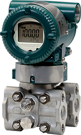
EJA-E系列的傳統安裝型差壓傳送器。
-
EJA115E
EJA-E系列差壓式流量傳送器,內建IFO流孔板。
-
EJA118E
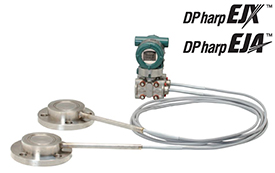
EJA-E系列的毛細管隔膜式差壓傳送器。
-
EJA130E
EJA130E是設計用於高靜壓環境的差壓傳送器。
-
EJA210E
專為液位應用設計的EJA-E系列法蘭安裝型差壓傳送器。
-
EJA310E
EJA-E系列中傳統安裝型的絕對壓力傳送器。
-
EJA430E
EJA-E 系列傳統安裝型表壓傳送器,需配定導壓配管。
-
EJA438E
EJA-E 系列法蘭安裝型表壓傳送器。
-
EJA440E
EJA-E 系列傳統安裝型表壓傳送器,需配定導壓配管。
-
EJA510E
EJA-E系列的管路安裝絕對傳送器。
-
EJA530E
EJA-E系列表壓傳送器,可直接安裝於管路上。
-
EJAC60E衛生級傳送器(Fluidless Type)
橫河電機推出了新版本的Fluidless系列– EJAC60E衛生級傳送器。
由具有衛生級檢測壓力功能的可更換製程接續口(總共16種接頭)組成。
適用於連接衛生級內的各種製程。 -
EJX110A
EJX-A系列的傳統安裝型差壓傳送器。
-
EJX115A
EJX-A 系列差壓式流量傳送器,內建IFO流孔板。
-
EJX118A
EJX-A系列的毛細管隔膜式差壓傳送器。
-
EJX120A
EJX-A系列的傳統安裝型微差壓傳送器。
-
EJX130A
EJX-A系列的傳統安裝式高靜壓差壓傳送器。
-
EJX310A
EJX-A系列的傳統安裝型絕對壓力傳送器。
-
EJX430A
EJX-A系列的傳統安裝表壓傳送器,需配定導壓配管。
-
EJX438A
EJX438A是EJX-A系列中的法蘭安裝型表壓傳送器。
-
EJX440A
EJX-A 系列傳統安裝型表壓傳送器,需配定導壓配管。
-
EJX510A
EJX-A系列的管路安裝型絕對壓力傳送器。
-
EJX530A
EJX-A 系列表壓傳送器,可直接安裝於管路上。
-
EJX610A
EJX-A系列的高性能管路安裝型絕對壓力傳送器。
-
EJX630A
EJA-A系列高性能表壓傳送器,可直接安裝於管路上。
-
EJX910A
This transmitter precisely measures differential pressure, static pressure, and process temperature; then uses these values in a high-perfomance on-board flow computer to deliver fully compensated Mass Flow.
-
EJX930A
Designed specifically for high static pressure applications, this transmitter precisely measures differential pressure, static pressure, and process temperature; then uses these values in a high-perfomance on-board flow computer to deliver fully compensated Mass Flow.
-
EJXC40A (DRS)
數位遠端感測器(DRS)傳送器透過專用通訊電纜,遠端連接master(高壓側)和slave(低壓側)sensor,測量壓差。
-
EJXC50A, EJAC50E (表壓直接密封)
直接安裝的法蘭密封系統由表壓傳送器和單顆直接安裝法蘭密封組成。
-
EJXC80A, EJAC80E (差壓/表壓式法蘭安裝)
法蘭系統由差壓或表壓傳送器組成,附帶一個或兩個法蘭(隔膜密封)。
-
EJXC80A, EJAC80E (差壓直接安裝式法蘭密封)
直接安裝式的法蘭密封系統由差壓傳送器和單個直接安裝法蘭密封組成。
-
EJXC81A, EJAC81E (絕對壓力法蘭安裝)
絕對壓力法蘭系統由絕對壓力傳送器和法蘭(單隔膜密封)組成。
-
低流量
使用伯努利原理,差壓傳送器可推算經過管道流體的流動。
-
壓力傳送器
橫河電機壓力傳送器,可以對製程壓力進行準確且穩定的測量,支援安全、可靠和獲利的工廠營運。
-
差壓
差壓(DP)定義為兩個壓力之間的差異。 差壓傳送器使用低壓側壓力的參考點,並與高壓側壓力進行比較。 儀器中的接口標記為高側和低側。
-
法蘭安裝
法蘭安裝型 (隔膜密封系統)可用於測量液體,氣體或蒸汽流量以及液位,密度和壓力。
-
液位
準確的液位讀數與工廠的安全、穩定跟獲利的運作息息相關。 液位傳送器測量壓差推斷容器中的液位。
-
溫壓補償
溫壓補償壓力傳送器是市場上測量質量流量的其中一種技術。
-
絕對壓力
絕對壓力傳送器比較相對於絕對壓力的壓力值。 絕對壓力始終是正值。
-
衛生級
衛生型壓力傳送器專為衛生和製藥應用設計
-
表壓
我們的壓力傳送器可選擇多種安裝方式,並均可提供準確且可重複的測量。 由於它基於大氣壓力,因此易於處理並可用於各種應用。