


Industry-Leading Reliable Paperless Recorder
Power generation, process automation, and factory automation in manufacturing industries require rigorous, continuous monitoring in the control room. The GX paperless recorder series is Yokogawa's latest recorder offering for industrial automation.
The GX paperless recorder series is an industry-first multi-point touch panel, to improve intuitive and smart operator control. Users can scroll, pan, zoom historical data, and even write freehand messages on its dust-proof and water-proof display. The Yokogawa GX paperless recorder series delivers industry leading reliability and measurement accuracy. Its custom graphics accommodates application or process-specific displays, while a wide range of communication protocols guarantee compatibility with your network architecture. It's simple for operators to view and retrieve past data with automatic email and FTP notifications.
> NEW! Added the “Elapsed time calculation” function to easily measure operating time and processing time
> NEW! Added the “F value calculation” function required for the sterilization process
Easier to use and more convenient
Industry's first! AI Equipment / Quality Easy Predictive Detection
- Equipment/Quality Easy Predictive Detection(option):
By easily creating predictive detection models from past recorded data, you can detect prediction of abnormalities in manufacturing equipment and products at an early stage.

- Future Pen:
With no complicated settings, you simply register the channels that you want to monitor as future pens, draw the near future as waveforms.
> Click here for details on AI Predictive Detection and Future pen
> About AI related products : go to AI Product Solutions page
Supports the aerospace industry's AMS2750/NADCAP and the automotive industry's CQI-9 for heat treatment applications (option)
Schedule management for periodically executing calibration correction configuration and the like. Compliant with heat treatment standard CQI-9 adopted by major companies in the automotive industry.
> Heat treatment special site
Supporting FDA 21 CFR Part 11, EU-GMP Annex 11, and data integrity

The advanced security function provides safety to use. With the expansion of the advanced security function option (/AS), it corresponds to US FDA 21 CFR Part 11, EU-GMP Annex 11, and data integrity in accordance with ALCOA +.
> What is "ALCOA +"?
Download technical data:
Regarding analog measurement, we have summarized the frequently asked questions in [Basic], [Applied], and [Noise Countermeasures]. > Download
About OpreX
OpreX is the comprehensive brand for Yokogawa’s industrial automation (IA) and control business and stands for excellence in the related technology and solutions. It consists of categories and families under each category. This product belongs to the OpreX Data Acquisition family that is aligned under the OpreX Measurement category.
Details
Predictive monitoring with AI
Equipment/Quality Easy Predictive Detection
* Creating predictive detection models and profile waveforms requires the Equipment/Quality Predictive Detection tool (sold separately).
Easily determine the quality of processes and equipment with the Health Monitor function
By easily creating predictive detection models from past recorded OK/NG (Not Good) data and loading it into GX/GP, you can detect prediction of abnormalities in manufacturing equipment and product quality degradation at an early stage. And because health scores which show the degree of normal and abnormal data consider correlations among multiple data to make determinations, they can capture prediction of abnormalities that are difficult for humans to detect.
- Maximum number of channels: 20
- Shortest recording interval: 100 ms
- Target channels: I/O channel, math channel, and communication channel
- Files that can be used to create a predictive detection model:
[Yokogawa products] SMARTDAC+, DXAdvanced
[Other companies’ products] KEYENCE : TR-W1000 and TR-W500 csv file, CHINO : KR2000 and KR3000 csv file, EUROTHERM : 6100A and 6180A csv file

Health monitor function empowers you to:
- Perform maintenance and repair before equipment malfunctions and product quality degradation
- Quantify degrees of equipment deterioration and quality degradation
- Easily build equipment/quality predictive detection systems on site

Profile function delivers real-time warnings of abnormalities
By creating a profile waveform from past recorded data and loading it into GX/GP, this waveform can be used as a threshold for process values. Profile waveforms are useful in applications where process values change over time. Also, you can see the deviation from the reference waveform on the screen.
- Maximum number of channels: 20
- Shortest recording interval: 500 ms */MC option required

Profile function empowers you to:
- Monitor and set alarms for the entire process, including the initial rise
- Compare the current process values with the ideal waveform

Please refer to the application notes for the proven effects and use cases of predictive detection.


Free trial for 60 days!* Equipment/Quality Easy Predictive Detection
By creating predictive detection model and profile waveform, Cloud or Offline Equipment/Quality Predictive Detection tool (paid separately) is required. To use cloud version, you need to apply from the following site to create an account.
*There are some functional restrictions during the free trial period.
- Cloud version : Predictive detection model cannot be loaded on SMARTDAC + main unit. It is possible to load the profile waveform into the SMARTDAC + main unit.
- Offline version : Neither of the sign detection model profile waveforms can be loaded into the SMARTDAC + main unit.
> Click here to apply for the cloud version
> Click here to download the offline version
*Search "OE10" on the member's site.
Note: Cloud version is available only for US, Canada, EU and UK.
Draw predicted future data with AI
AI comes standard on the GX/GP. No complicated settings. Simply register channels, and you're ready to draw future measured data on those channels.
Future Pen
Use acquired data to predict future data, and display predicted future waveforms along with real time data on the trend monitor. Predicted future waveforms help you identify and deal with likely problems as soon as possible.
- Max. channels: 10
- Shortest recording interval: 1 sec.
- Prediction range: Recording interval x 60 points

Future alarms
You can set future alarms based on future data predicted by the future pen. You can check future alarm information in the Future Alarm Summary screen. Also, when a future alarm occurs, notification can be sent by external (digital) output or email. Because the future alarm information also includes the predicted alarm time, you can also identify the urgency.

* Effective for relatively slowly fluctuating data. Not suitable for rapidly fluctuating data.
* Certain restrictions apply with the future pen function. See the general specifications for details.
Future Pen Demonstration for Predictive Detection
- What is a future pen?
- What is a future alarm?
- Examples of using future functions
- Further AI Analysis
(Approximately 3 minutes and 30 seconds)

> Please refer to this video. (open in new window)
An intuitive UI engineered for ease-of-use
Efficiently search for key data
Easily review historical data
Seamless display of historical trends—flick or drag the trend display to scroll through the data, even during measurement.

Quickly find data using calendars and summary screens
From a calendar, jump to waveforms of a specific date. From the alarm summary, jump to the waveform active during the alarm.

Easily check off trouble spots
Write freehand messages
Immediately clear areas of concern with a hand-written message. ou can draw or hand-write on the waveform area using a stylus or the tip of your finger.

Save and output image files
Save trend waveforms of interest or screens displayed during alarms as image (PNG) files, and print them out at the same time.

Check waveforms of concern in detail
Display digital values at any location
Move the scale to display the value corresponding to that position as a numeric value. Instantly check maximum/minimum measured values.

[Patent technology]
Ascertain long-duration trends at a glance
All historical trends display
Long-duration trends can be fitted to a single screen for easy viewing.

All historical trends display
Zoom in/out - time axis and engineering units
The time axis and engineering axis can expanded and compressed using a simple pinch together or apart function

Pinch apart / Pinch together
Variety of display screens

Physical quantities are displayed and recorded on a log scale.
Log scale display (/LG option)

Multi-panel display
You can select from 9 layouts, and save up to 20 configurations. (Multi panel available on the GX20 only)

Built in control screens and display
Various pre-configured control screens and display are available.
Create your own screens
Custom display (/CG option)
You can arrange display objects such as trend, numeric, and bar graphs any way you like to create monitor displays that are customized to the environment. Start/stop pumps and perform other operations.

Custom display building software
DAQStudio DXA170
DAQStudio is software for creating custom displays. You can load screens you created onto the GX via Ethernet or external memory media (SD/USB) and display them.


Highly flexible and scalable architecture
Modular input/output
Inputs and outputs are modular for easy expandability. The GX multichannel paperless recorder main unit alone provides up to 100 channels (GX20) of measurement.

Wide variety of input/output modules
Select from a wide variety of input/output modules.

| Model | Name | Measurement/Application | Channels |
|---|---|---|---|
| GX90XA-10-U2 | Analog input module | DC voltage, DC current (with external shunt resistor connected), thermocouple, RTD, contact (solid state relay scanner type) | 10 |
| GX90XA-10-L1 | DC voltage, DC current (with external shunt resistor connected), thermocouple, contact (Low withstand voltage solid state relay scanner type) | 10 | |
| GX90XA-10-T1 | DC voltage, DC current (with external shunt resistor connected), thermocouple, contact (electromagnetic relay scanner type) | 10 | |
| GX90XA-10-C1 | DC current (mA) (solid state relay scanner type) | 10 | |
| GX90XA-10-V1 | DC voltage, DC current (with external shunt resistor connected), thermocouple, contact (Solid state relay scanner type) | 10 | |
| GX90XA-04-H0 | DC voltage, DC current (with external shunt resistor connected), thermocouple, RTD, contact (individual A/D type) | 4 | |
| GX90XA-06-R1 | 4-wire RTD, 4-wire resistance (solid state relay scanner type) | 6 | |
| GX90YA | Analog output module | Current output | 4 |
| GX90XD | Digital input module | Remote control input or operation recording | 16 |
| GX90YD | Digital output module | Alarm output | 6 |
| GX90WD | Digital input/output module | Remote control input or operation recording/alarm output | DI:8/DO:6 |
| GX90XP | Pulse input module | Pulse signal data acquisition, integral count | 10 |
| GX90UT | PID control module | PID control (2 loop) | AI:2/AO:2 DI:8/DO:8 |
* For details on each module, refer to the general specifications.
You can also select modules using the convenient selection tool Product Finder.
Expandable to up to 450 channels (real actual input)
Supports up to 450 channels of measurement. Note that if MATH and communication channels are included, the GX20 large memory type can record on up to 1000 channels. The GX main unit and expandable I/O can both use the same input/output modules.

You connect directly with a LAN cable without connecting through a hub or repeater. * You can also connect subunits of the GM Data Acquisition System.
| Model | Type | Max.channels | Number of channels by configuration | |
|---|---|---|---|---|
| GX10 | Standard | 100ch | Main unit only | 0-30 |
| Main + expandable I/O | 0-100 | |||
| GX20 | Standard | 100ch | Main unit only | 0-100 |
| Main + expandable I/O | 0-100 | |||
| Large memory | 450ch | Main unit only | 0-100 | |
| Main + expandable I/O | 0-450 | |||
The number of channels is for analog input only.
Reduce wiring with distributed installation
When the recorder is installed offsite (away from the DUT), you can place the expandable I/O at the site and monitor data without the need for long-distance wiring of thermocouples and other sensors.

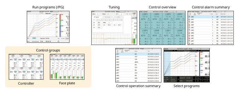
Wide variety of convenient PID control
PID and program control
- PID control module
2-loops per module, up to 20 loops per system - Setpoint program control function (/PG option)
Up to 99 patterns

Real time remote monitoring from a web browser
Through a Web browser you can monitor the GX in real time and change settings. You can easily build a seamless, low-cost remote monitoring system with no additional software.
Real time monitoring screen
You can view monitor screens in real time that are identical to the trends, digital, and other displays on the GX main unit.

*Notice on Java Plug-in running in Web browser for SMARTDAC+ series
Enter settings online with a web browser
The setting screen lets you copy AI channel settings and other information to Excel for editing. You can reimport the data into the setting screen after editing.

Dedicated software (free download) is available for loading waveforms and GX/GP settings
Universal viewer
Data files saved on the GX/GP can be viewed and printed. You can perform statistical computation over an area and export to ASCII, Excel, or other formats.

Offline setting software
Save settings or transfer them to the GX/GP.

Supports the aerospace industry's AMS2750/NADCAP and the automotive industry's CQI-9 for heat treatment applications
Calibration correction schedule control function (/AH option)
Schedule management for periodically executing calibration correction configuration and the like. The correction factor can be set separately for unit and sensor dependency. For AMS2750, we offer TUS software* that can easily create TUS (temperature distribution test) reports.*.
* For information on TUS software, contact your Yokogawa representative.

Record data in separate files per equipment set
Multi-batch Function (/BT option)
Recorder pre-defined channel groups to separate data files with independent start and stop control. Up to 12 independent batches can be created.

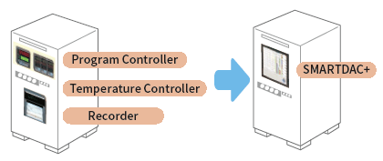
Seamless integration
Combine and integrate complex legacy control panel into a simple and flexible data acquisition station.
High speed measurement (down to 1 ms)
Yokogawa's proprietary A/D converter allows the high speed module to measure data points as fast 1ms.
- High speed (1 ms) measurement*
- Proprietary A/D converter
*With 1ch per module. At 2 ms, 2 ch per module, and at 5 ms or more, all 4 ch per module.
| Model | Scan interval | ||
|---|---|---|---|
| 1ms | 2ms | 10ms | |
| GX10 | 1ch | 5ch | 10ch |
| GX20-1 | 1ch | 5ch | 10ch |
| GX20-2 | 5ch | 25ch | 40ch |

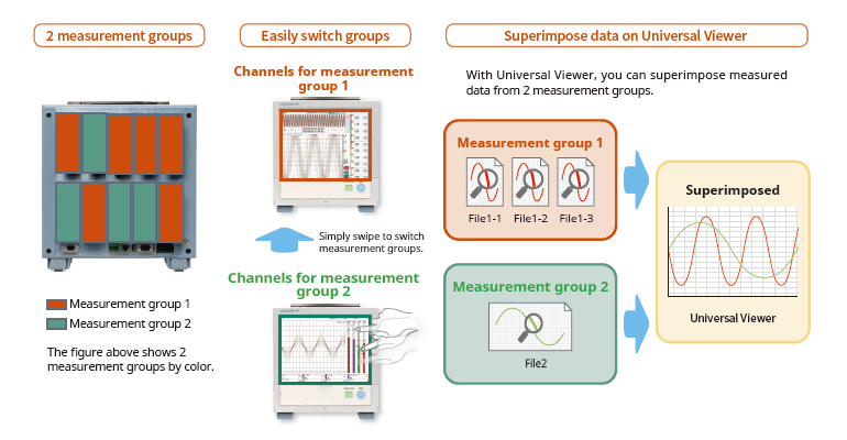
Dual interval measurement with two different scan intervals
Users have the ability to choose two different scan intervals on a single GX/GP system. This allows users the flexibility to measure various types of inputs with two different scan intervals in a single system. For example, this provides for efficient, simultaneous measurement of signals with slow fluctuations such as temperature, and fast-changing signals such as pressure and vibration. Modules can be assigned to measurement groups.
MATH (including reports), and event actions
MATH function (/MT option)
Supports various kinds of math computation, including basic math and functions (square root, logarithms, trigonometry). Write formulas using variables for measured or computed data and save or display the results―this saves time and effort on post-processing. Create hourly, daily, monthly, and other reports with the Report function.

Event actions
Ability to assign actions tied to specific events during the operation of the data acquisition station.

Elapsed time calculation
Elapsed time calculation allows you to measure the amount of time elapsed after a condition is met. The measured time can be recorded through math channels.
F-value calculation
F-value calculation allows you to measure the lethal value of bacteria. The measured value can be recorded through math channels.

Report creation and network functions (/MT option)
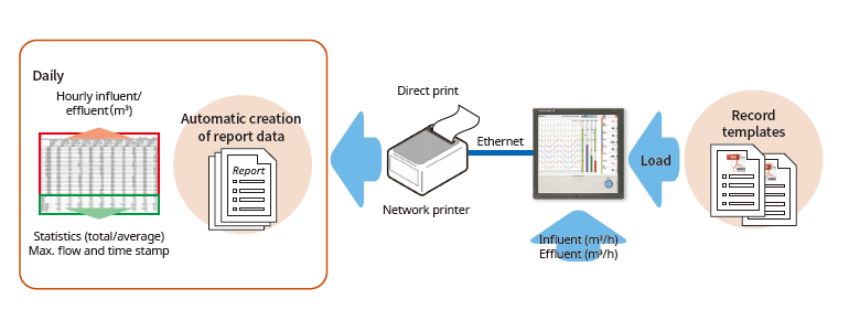
Provides a variety of convenient networking functions
Modbus/TCP and Modbus/RTU Communications
GX supports Modbus TCP/IP client and server modes for Ethernet communications and Modbus RTU master and slave modes for optional serial communications.
Modbus/TCP (Ethernet connection)
Using the Modbus/TCP and Modbus/RTU functions, you can display and save data from the server and slave devices on the GX.*
* Requires the communication channel (/MC option ).

Modbus/RTU (RS-422/485 connection)
Using the Modbus/TCP and Modbus/RTU functions, you can acquire GX data from upstream devices.

(Connect up to 16 Modbus/TCP servers, or up to 32 for the GX20-2.)
(Up to 31 Modbus/RTU slaves can be connected.)
EtherNet/IP Function (/E1 option)
Using the EtherNet/IP server function, you can access the GX from a PLC or other device to read measurement/computation channels and write to communication input channels (GX10: up to 500ch, GX20-1: up to 300ch, GX20-2: up to 500ch). Communication channel function (/ MC option) is required.
In addition, the following operations required for batch processes can be performed through the PLC using Explicit messages.

Note: Explicit message operation in OMRON PLC has not been confirmed.
CC-Link family SLMP communication (/E4 option))
Protocol function that enables connection from a GX to Mitsubishi Electric PLCs without sequencer programs. You can run the GX as an SLMP client, enabling writing of GX measured data to the PLC and writing of PLC data to communication channels.*
*Requires the communication channel function (/MC option).

PROFINET communication (GX90NW Network Module)
By using the GX90NW network module, you can connect the GX/GP as a secondary I/O device via PROFINET. You can access the GX/GP from the PLC or other I/O controller, read measurement/math channels, and write to communication channels*. You can easily perform necessary operations for batch processes from the PLC.
* Communication channel function (/MC option) is required.

Powerful tool for instrument performance evaluation testing (/E2 and /MC options)
Highly precise measured data from power measuring instruments (WT series power analyzers) can be acquired without loss of fidelity on the GX, and recorded and displayed alongside the GX's own measured data. This is ideal for performance evaluation testing because you can record instrument power consumption, temperature, and other phenomena simultaneously.
- Models that can be connected:
Yokogawa Test & Measurement Corp., WT series power analyzers,
WT300/WT300E (command mode WT300), WT500, WT1800/WT1800E (command type WT1800)) - Max. no. of connections: 8 (GX10), 16 (GX20)

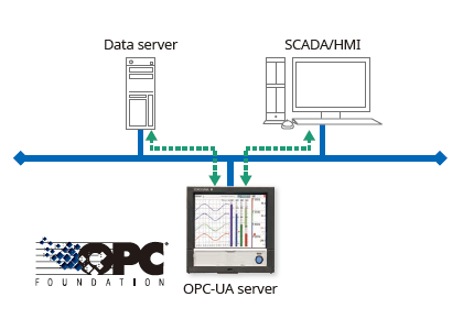
OPC-UA Server (/E3 option)
Data acquired by the GX can be accessed through Ethernet communication from a host system (OPCUA client). Writing from an upstream system to a GX communication channel requires the communication channel function (/MC option).
DARWIN-compatible communication
The GX supports DARWIN communication commands. Use your current DARWIN communication programs as-is on the GX.*
* See your dealer or nearest Yokogawa representative for details.

CENTUM/STARDOM communication package
- CENTUM: LFS2432, DARWIN/DAQSTATION Communication package (for ALE111 [Ethernet])
- STARDOM: NT365AJ DARWIN connection package
FTP-based file transfer
The FTP client/server functions allow you to easily share and manage data from a centralized file server.

E-mail messaging function

Automatic network setup (DHCP) function
GX uses SNTP protocol in client mode to acquire time information from a network time-server. This function allows any number of GX units within a facility to have precisely synchronized time; all units will record data with coordinated date and time stamp information. In addition, GX can function as a server, providing time data to other SNTP client units on the network.

Time synchronization with network time servers
GX uses SNTP protocol in client mode to acquire time information from a network time-server. This function allows any number of GX units within a facility to have precisely synchronized time; all units will record data with coordinated date and time stamp information. In addition, GX can function as a server, providing time data to other SNTP client units on the network.

Rock-solid hardware and highly secure
Be confident that recorded data is saved
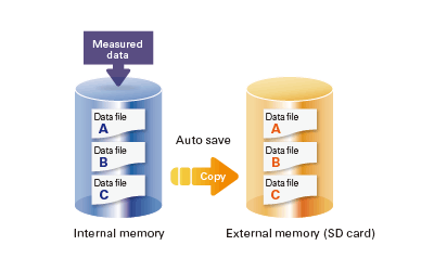
Measured and calculated data is continuously saved to secure, internal non-volatile memory. At manual or scheduled intervals, the files in memory are copied to the removable media. In addition, the files can be copied and archived to an FTP server.
Because of the inherent reliability and security of non-volatile memory, the possibility of losing data under any operating condition or power failure event is extremely small.
Select file formats according to your application
For increased security, measured data can be saved in binary format. This format is very difficult to decipher or modify in traditional text editors or other programs. To enable easy and direct opening of the data in text editors or spreadsheet programs, choose text format. This allows you to work with your measurement data without dedicated software.

Security enhancements
Safely sends and receives customer data.

SSL: An encryption protocol for data sent over TCP/IP networks.
Front panel door lock
The front panel door can be locked to prevent mishandling of the power switch or external media.

Analog front end module
A proprietary A/D converter delivers high speed, high precision data acquisition. (High-speed AI, PID Control module)

Standards supported
GX supports various standards such as CSA, UL, CE/EMC Directive/CE/Constant Voltage Directive, European RoHS Directive, WEEE Directive, RCM, KC Mark (Korea).

Strict security measures
Advanced security function option (/ AS) corresponding to strict requirements for data management
SMARTDAC+ GX /GP/GM advanced security function option (/AS) provides safe and traceable data management in applications such as pharmaceutical manufacturing, biotechnology, health management and medical institutions.
The advanced security function supports the strict requirements of US FDA 21 CFR Part 11, EU-GMP Annex 11 and other associated guidelines for data management.
It also supports data integrity in accordance with ALCOA+ (Attributable, Legible, Contemporaneous, Original, Accurate, Complete, Consistent, Enduring, Available) mentioned in PIC/S, WHO, MHRA and FDA guidance documents.
What is "ALCOA +"?
It refers to A: attribution, L: legibility, C: simultaneity, O: originality, A: accuracy, C: completeness, C: consistency, E: Persistence, and A: Availability. ALCOA + is a requirement for data integrity guidelines of PIC / S (Pharmaceutical Testing Contract and Pharmaceutical Testing Joint Scheme), WHO (World Health Organization), MHRA (Pharmaceuticals and Drug Regulatory Authority: UK), and FDA (Food and Drug Administration).
Secure electronic records
Measured data, settings, and operation logs, are saved to a single encoded binary file. Encoded data in binary format offers a high level of security because it cannot be opened in most text editors.
If the data files are damaged or tampered with, SMARTDAC+ Standard Universal Viewer software will identify the nonconformity and notify the user accordingly.
Security data file transfer
SMARTDAC+ can automatically transfer data to an FTP server. FTPS, which encrypts data transferred via FTP using SSL, is also supported, allowing data files to be transferred safely.

Electronic signature(data record signing) function
Measurement data can be displayed and confirmed on the GX/GP (only the data in the internal memory) or the SMARTDAC+ Standard Universal Viewer software, and an electronic signature can be applied to that data. Three levels of signature are available: operator, supervisor and quality control. The signature along with information such as pass/fail and comments can be saved to the data for review and audit.
*Electronic signature to the GM is possible only from the SMARTDAC+ Standard Software. Electronic signature cannot be applied through GM's web server.

Logical security
Data integrity requires that the right users have access to the right information.
SMARTDAC+ can create users with various access privileges.
- Four main security levels (two separate administrator roles, user and monitor user).
- Up to 200 persons can be registered.
- Process owners/ system owners can be given access rights to functionality appropriate to their role.
- For the password, a minimum string length and a minimum policy complexity can be set.
- Centralized management of user names and passwords using servers on the network is possible through ActiveDirectory.

Audit trail function
The SMARTDAC+ operation log is saved to a file along with measurement data.
When settings are changed, it is possible to record the reason for the change along with the setting change operation. In addition, checking the details of setting changes from "setting difference operation history" makes greatly reduces the data checking work during audits.

Free dedicated software download
SMARTDAC+ Standard Software is possible to display measurement data, display the operation log, and configure the GX/GP/GM. It is also possible to sign in data using the SMARTDAC+ Standard Universal Viewer.
Universal Viewer software
The Universal Viewer software can display data files in various forms such as waveforms and numeric values. It can display and print not only measurement data but also alarm and message lists and operation logs. With the operation log, a comparison of the settings before the change and those after the change can be displayed, allowing you to check the changes in detail.
It is also possible to sign the data by entering the user name, user ID and password after confirming the measurement data. If the data has already been signed, you can sign at a different level after confirming the signature state on the screen.

Hardware Configurator software
Hardware Configurator software allows for offline system configuration which can be imported via SD memory or external storage media as well as Ethernet communication. System settings can be printed in a table format to support GX /GP/GM system validation (IQ/OP/PQ).
In addition, a pair of selected setup data files can be compared, and their differences can be displayed and printed in table format.

Validation documentation
Validation documentation (sold separately) is a validation protocol template that simplifies GX/GP/GM and SMARTDAC+ Standard system validation. The document is provided on the Yokogawa website as an MS Word file for easy editing.*
*The validation and document verification are the customer’s responsibility.
Zdroje

Okinawa Cellular Telephone Company has launched an experimental vegetable factory to encourage farmers in the prefecture to enter into that business. The 80 square meter vegetable factory engages in hydroponics, and uses 100% artificial lighting. Located at Nanjo City in the southern part of Okinawa island, the facility holds six levels of beds dedicated to raising greens like romaine and leaf lettuce.

S&B Sankyo uses the GX20 Paperless Recorder to monitor temperature and pressure in a food processing plant's sterilization process.

One important risk to manage with regard to coal stacks is preventing fires due to spontaneous combustion.

Continuous technology improvement is ongoing in the pulp & paper industry to obtain the best possible performance. The improved plant performance translates to the higher quality improvement and lower cost, and simultaneously environmental friendly plant operation.


The SMARTDAC+ GX Series monitor furnace temperature in tunnel kiln furnaces and the like using Faceplate and Trend screens that come as standard features.

This recorder can efficiently control the heat treatment process, which is a critical control point (CCP) of HACCP, a hygiene management method in the food production process . It measures and records F values and elapsed time in the sterilization process of food and pharmaceuticals.

The GX20 and GX90UT offer an average value computation function making it ideal for controlling temperature and other fluctuating phenomena. The operating status can be controlled in real time, providing operating cost reductions.

Performing control while changing the set point temperature moment by moment is called running a program pattern (or simply running a program). Sterilization and pasteurization require maintaining specific temperatures for specific durations.

The SMARTDAC+ GX is an ideal instrument for program control of a vacuum heat treatment furnace, and recording of subsequent data. A screen is available for monitoring of the program status.

Pressure measurement of tubeless tyres to monitor the air loss is one of the key performance tests in the tyre manufacturing units. Relocation of tyres from one testing rack to the other for various tests and frequent movement of the testing setup for conditional tests to various locations calls for cable free implementation for ease of handling.

AN 04L51B01-01EN

AN 04L51B01-02EN

The SMARTDAC+ recorder monitors wind direction and speed on-site or remotely, and sends instant email notifications if wind speed exceeds a specified threshold. This not only helps ensure safe loading and unloading of cargo at ports, but also prepares for natural disasters.

SMARTDAC+ GX series records the clean room temperature, humidity, atmospheric pressure, door openings and closings, etc.

AN 04L51B01-03EN

By using the Multibatch function (an option added with SMARTDAC+), you can efficiently record data from multiple devices onto a single SMARTDAC+.

The sterilization temperature prior to the filling process is monitored in the field or office. The temperature data is recorded in an external storage medium.

By using the computation function of the SMARTDAC+ series Paperless recorder GX/GP, computation option computes the "F-value," or sterilizing value for the sterilization process, so that the computation results can be recorded in the form of data.

- For remote monitoring (of temperature, pressure, and flow volume), installing the SMARTDAC+ GM in the plant and the SMARTDAC+ GX in the office provides for a scalable, pc-free on-site data monitoring solution.
- You can centralize management of large quantities of data by automatically transferring acquired data to a FTP server.

- Universal inputs provide support for thermocouple, RTD, voltage, and a variety of other input signals.
- Lineup of models for up to 450 inputs.
Allows multipoint monitoring and recording on a single unit. - Easily enables network-based data management.
file transfers, Web monitoring, and alarm e-mail

Multi-touch technologies have rapidly moved from the commercial to the industrial sector where they are being used to enhance data analysis.
Downloads
Brožury
- SMARTDAC+ Data Acquisition & Control Paperless Recorder GX/GP (9.8 MB)
- SMARTDAC+ Aerospace Heat Treatment (Option /AH) (1.2 MB)
- SMARTDAC+ series Easy connection to PROFINET devices (787 KB)
- SMARTDAC+ Automotive Industry Heat Treatment (Option /AH) (1.0 MB)
- SMARTDAC+, the best-selling paperless recorder (data logger), now supports PROFINET! (1.3 MB)
- SMARTDAC+ Advanced Security Function Data Integrity Support for pharmaceutical & medical standards (1.3 MB)
- AI Product Solution Book Download
- Yokogawa in the Pharmaceutical Industry (7.7 MB)
Instrukční manuály
- Precaution on the use of SMARTDAC+ (664 KB)
- Model GX10/GX20/GP10/GP20 Paperless Recorder First Step Guide (20.9 MB)
- Model GX10/GX20/GP10/GP20 Paperless Recorder User’s Manual (14.7 MB)
- Model GX10/GX20/GP10/GP20/GM10 Communication Command User's Manual (3.6 MB)
- Handling of the SD Memory Card (321 KB)
- SMARTDAC+ STANDARD Universal Viewer User's Manual (4.2 MB)
- Model GX10/GX20/GP10/GP20/GM10/GX90NW PROFINET Communication User's Manual (4.5 MB)
- Model GX10/GX20/GP10/GP20 Advanced Security Function (/AS) User’s Manual (4.9 MB)
- Cloud Equipment/Quality Predictive Detection Tool User’s Manual (166 KB)
- Model GX10/GX20/GP10/GP20/GM10 WT Communication (/E2) User’s Manual (1.5 MB)
- Model GX10/GX20/GP10/GP20/GM10 EtherNet/IP Communication (/E1) User’s Manual (1.8 MB)
- Regarding the Downloading and Installing for the Software, Manuals and Labels/About the Usage of Open Source Software (367 KB)
- Model GX10/GX20/GP10/GP20/GM10 Log Scale (/LG) User’s Manual (1011 KB)
- SMARTDAC+ STANDARD Hardware Configurator User's Manual (4.4 MB)
- Model 773230 Downloading the Validation Documents (132 KB)
- Model GX10/GX20/GP10/GP20/GM10 Multi-batch Function (/BT) User’s Manual (3.5 MB)
- Model GX10/GX20/GP10/GP20/GM10 OPC-UA Server (/E3) User’s Manual (884 KB)
- Model GX10/GX20/GP10/GP20/GM10 SLMP Communication (/E4) User's Manual (2.1 MB)
- GX20/GP20 (/CM2 and /CM3 options), GM10 (/CM2, /CS2, /CM3 and /CS3 options) 920MHz wireless communication First Step Guide_US,KR (1.3 MB)
- Model GX10/GX20/GP10/GP20/GM10 Loop Control Function, Program Control Function (/PG Option) User’s Manual (24.3 MB)
- Notes on using the Model GX90EX expansion module (I/O expansion module) (194 KB)
- DXA170 DAQStudio User's Manual (4.8 MB)
Všeobecné specifikace
- GX10/GX20 Paperless Recorder (Panel mount type) (3.9 MB)
- GX60 I/O Base Unit (Expandable I/O), GX90EX Expansion Module (3.1 MB)
- GX90XA/GX90XD/GX90YD/GX90WD/GX90XP/GX90YA I/O Modules (4.6 MB)
- GX90UT PID Control Module, GX10/GX20/GP10/GP20, GM, Loop Control Function, Program Control function (/PG) (1.8 MB)
- Equipment/Quality Predictive Detection Tool (340 KB)
- GX90NW Network Module (1.4 MB)
- Model 773230 Validation Document for SMARTDAC+ (for the /AS option) (355 KB)
- 415940, 415941 and 415942 Shunt Resistor for Screw Input Terminal (178 KB)
- 438920, 438921 and 438922 Shunt Resistor for Clamp Input Terminal (252 KB)
- List of RoHS (2011/65/EU) Directive Compliant Products (6-substances RoHS compliant products) (356 KB)
- New Legislative Framework (NLF) Conforming Products (362 KB)
- GX20/GP20 (/CM2 option) GM (/CM2 and /CS2 options) 920MHz Wireless Communication (2.3 MB)
- List of the US Toxic Substances Control Act (TSCA) Compliant Recorder and Controller Products (176 KB)
- List of EU RoHS Directive “2011/65/EU+(EU)2015/863” (10-Substances) Compliant Recorder and Controller Products (324 KB)
Software
- Hardware Configurator *Log-in Required
- Universal Viewer *Log-in Required
- GA10 Data Logging Software *Log-in Required
- GA10 Data Logging Software [60-day free trial] *Log-in Required
- DAQStudio (DXA170) Revision Upgrade *Log-in Required
- Offline version: Equipment/Quality Predictive Detection tool OE10 *Log-in Required
- Validation Document for SMARTDAC+ *Log-in Required
- PLC Communication Protocol Profile (EDS file) for GX/GP (For connecting OMRON's PLCs) *Log-in Required
- SMARTDAC+ Report Template Builder *Log-in Required
- SMARTDAC+ PROFINET GSDML file *Log-in Required
- SMARTDAC+ Excel Report Simulator *Log-in Required
- SD Card Formatter *Log-in Required
- GX/GP Firmware *Log-in Required
- SMARTDAC+ I/O Module Firmware *Log-in Required
- SMARTDAC+ SettingFileConverter Settings File Conversion Tool *Log-in Required
- SMARTDAC+ I/O Expansion Module Firmware *Log-in Required
- Tag Plate *Log-in Required
- EtherNet/IP Profile (EDS file) for GX/GP *Log-in Required
- Mobile WEB Application for GX/GP/GM *Log-in Required
- LabVIEW Driver (for SMARTDAC+ Series) *Log-in Required
- SMARTDAC+ High-speed Analog Input Module Firmware *Log-in Required
- SMARTDAC+ PID Control Module Firmware *Log-in Required
- MH920 Wireless Communication module (Coordinator) Firmware *Log-in Required
Technické informace
- Effectively Using SMARTDAC+; Software Introduction (6.1 MB)
- SMARTDAC+ Advanced Security Functions White Paper for FDA 21 CFR Part 11 (587 KB)
- Reduce Risk by Eliminating Paper Chart Records (1.6 MB)
- GX/GP Custom Display Setup Guide (642 KB)
- Recorders, Data Loggers, and Control Products Security Standard (488 KB)
- DARWIN Replacement Guide (9.1 MB)
- High-speed Measurement Application High-speed Measurement/ Dual Interval Measurement Feature LR Replacement (8.9 MB)
- SMARTDAC+ Loop Control Function, Program Control Function (/PG Option) (9.5 MB)
- SMARTDAC+ CX Replacement Guide (Model and Suffix Code Replacement) (2.2 MB)
- SMARTDAC+ GX/GP/GM Advanced Security Function (/AS) Functional Differences for Supporting Data Integrity (3.8 MB)
- Heat Treatment Applications in the Aerospace and the Automotive Industry *Registration required
- Connect Siemens S7-1200 PLC to SMARTDAC+ with GX90NW (PROFINET Communication) (3.4 MB)
Výkresy
- Paperless Recorder GX10 (828 KB)
- Paperless Recorder GX20 (976 KB)
- Expandable I/O GX60 (575 KB)
- Expansion Module GX90EX (207 KB)
- PID Control Module GX90UT (219 KB)
- Digital Input/Output Module GX90WD (229 KB)
- Analog Input Module GX90XA (531 KB)
- Network Module GX90NW (344 KB)
- Digital Input Module GX90XD (378 KB)
- Pulse Input Module GX90XP (329 KB)
- Analog Output Module GX90YA (265 KB)
- Digital Output Module GX90YD (267 KB)
- SMARTDAC+ Series 2D CAD *Log-in Required
Videa

Smart user interface, smart architecture, and smart functionality is achieved in the new Yokogawa SMARTDAC+ data acquisition and control product series. The Yokogawa SMARTDAC+ GX and GP are fully integrated measurement, display, and recording platforms equipped with an advanced touch screen operator interface. GX series is a panel-mount design, capable of operating in harsh industrial applications and environments. GP is the portable version of the GX, intended for use in lab and test bench applications.

YOKOGAWA aspires to establish Smart GMP manufacturing facilities that provide consistent quality and supply while eliminating industrial waste, enhancing productivity and always using high-quality component parts and materials.


By equipping SMARTDAC+ with the advanced security features option "/AS", it meets the strict requirements of the U.S. FDA 21 CFR Part 11 and supports DI in compliance with PIC/S and ALCOA+ by WHO, MHRA and FDA.

YOKOGAWA creates autonomous operations with high-efficiency automation and optimization that allows growth with minimal deployment of manpower.

This short video introduces SMARTDAC+ GX20 Data Acquisition Station and demonstrates how quickly we can set the unit up to do measurement and data recording.

This short video shows the method of adding input/output modules to the Yokogawa SMARTDAC+ Data Acquisition recording system and how to confirm correct installation.

This short video shows the method of configuring alarms on the SMARTDAC+ paperless recorder. In this example setting a high alarm on channel 1 at 25 Deg C.

This short video shows the method of configuring group settings in SMARTDAC+ paperless recorder.

This short video shows the method of loading a configuration file stored on an SD card into a SMARTDAC+ paperless recorder.

This short video shows the method of configuring tag numbers in the SMARTDAC+ paperless recorder.

This video shows the capability of viewing information from the 21 CFR Part 11 compliant SMARTDAC+ paparless recorder range on an iOS or Android device
Novinky
-
Tisková zpráva | Řešení a produkty Apr 19, 2022 Yokogawa to Release Equipment/Quality Predictive Detection Tool for SMARTDAC+ Paperless Recorders and Data Loggers
-
Tisková zpráva | Řešení a produkty Jul 5, 2018 Yokogawa adds high-voltage analog input module to OpreX™ Data Acquisition lineup
Yokogawa adds high-voltage analog input module to OpreX™ Data Acquisition lineup.
Potřebujete víc informací o lidech, technologii a řešeních?
Kontaktuje nás