Introduction
Level transmitter configuration can be very time consuming. Calculations required to determine proper range values for traditional transmitters can become complex due to the physical layout of an application.
DPharp transmitters with advanced software functionality eliminate this time consuming task. With maintenance shops getting smaller, finding equipment that allows us to do more with less becomes a priority.
Application
Using typical smart or conventional products all of the following must be considered:
- The specific gravity (SG) of the process;
- Precise location of 0% and 100%;
- Specific gravity of the capillary fill fluid or sealing liquid (for impulse tubing);
- Vertical height of capillary or impulse piping;
- Exact orientation of the transmitter to the vessel;
- Vertical distance between the flanges.
Depending on the application, the vessel may be open (referencing atmosphere), or closed (under some blanket pressure).
Elevation is typically used when the vessel is closed. To reference blanket pressures, a low side wet leg or remote seal must be used. The low side pressure creates a negative force on the transmitter equal to the vertical height times the specific gravity of the fill fluid.
Suppression is positive pressure created on the high side of the transmitter typically due to a zero point above the transmitter. It is normally employed in an open vessel referencing atmosphere. This is a positive pressure equal to the vertical distance between the 0% point and the transmitter times the specific gravity of the liquid.
Elevation/suppression distance almost never agrees with the piping and instrumentation diagram (P&ID) because actual piping (or remote seal capillaries) do not form exacting angles in the field. In most cases, the precise vertical height is not known until the unit is installed.
Span is the vertical distance of the process times the specific gravity: Figure 1. 10.5 * 0.9 = 9.45 mH2O (31.5 inH2O).
Calibration range is the calculated 0 and 100% taking into consideration positive and negative pressures. In figure 1, the following applies:

Figure 1
0 % = H - L
= ( 4.5 x 0.8 ) - ( 15 x 0.8 )
= 3.6 - 12
= -8.4 mH2O ( -28 inH2O )
100 % = H - L
= ( 4.5 x 0.8 ) + ( 10.5 x 0.9 ) - ( 15 x 0.8 )
= 3.6 + 9.45 - 12
= 1.05 mH2O ( 3.5 inH2O )
The calibration range is: -8.4 to 1.05 mH2O ( -28 to 3.5 inH2O )
Note: SG stands for specific gravity.
The information required to perform the calculation is not readily available. It exists in vendors instruction manuals, P&ID's, but not until the unit is actually installed will all the variables be known because the process piping and capillaries do not form exacting angles in the field.
Solution
DPharp has a smart level setup feature that eliminates the need for elevation/suppression calculations, making set up quick and painless.
Calibration is accomplished by simply following these four steps (for Brain):
- Span the transmitter to the process, height * specific gravity of 0 to 9.45 mH2O (0 to 31.5 inH2O) using the BT200 in C21: LRV and C22: HRV.
- Install to the process using either capillaries or impulse tubing.
- Bring the process to a zero (4mA) condition.
- Through the BT200 execute H10: Auto LRV in the H: AUTO SET menu.
DPharp will calculate the total elevation/suppression and automatically setup the device for that installation. It will even correct the values in software at C21: LRV -28 and C22: HRV 3.5 so the customer can print and record the actual configuration for their maintenance documents.
But what if I cannot bring my process to zero? I have installed the unit, fluid is now in the tank, and the output of the transmitter does not agree with my sight glass. What do I do?
Most transmitters can only make adjustments at 0% or 100%. DPharp can make adjustments anywhere with full elevation or suppression. Once the transmitter is programmed with the correct span, all that is needed is a known point in the process (usually provided by the sight glass.) The output can be adjusted in one of two ways.
- Simply adjust the encoder on the DPharp until the output reaches the known point. In figure 1, the output would be adjusted to 60%.
- The correct value can be entered into J10: Zero Adj. In the case of this example, the proper output value of 60% would be entered. The amount of deviation can be viewed in J11: Zero Dev.
DPharp's digital sensing technology makes this possible. With analog sensing technologies (like capacitance sensors), range changes often necessitate a re-calibration or a trimming of the A/D converter to achieve specified performance. The digital DPharp sensor has no A/D converter, no trimming is necessary. The new range is guaranteed to perform within specification.
Notes
- In level measurement, it is important to maintain a consistent reference pressure. On a closed tank system, this is most efficiently achieved by the use of remote seals and capillary systems.
- It is important to note that the span is to be calculated on process height x specific gravity of the process fluid, and will not necessarily agree with the physical height.
- Output will be linear to the level, regardless of fluid or blanketing system.
- Use of remote seals eliminates problems such as condensation in impulse piping, the requirement for maintenance of condensate pots and fill fluid leaking into the process.
Main Features of DPharp
- ±0.03% Overpressure calibration protection
- ±0.1% per 10years long term stability
- 100:1 turndown
- ±0.055% accuracy
- SIL2 standard
- ±0.1% per 15years long term stability
- 200:1 turndown
- Best-in-class high accuracy, 0.04%
- Multi-sensing output
- Multi-variable transmitter as EJX family line-up
- SIL2 standard
Verwandte Industrien
-
Power
In the mid 1970s, Yokogawa entered the power business with the release of the EBS Electric Control System. Since then, Yokogawa has steadfastly continued with the development of our technologies and capabilities for providing the best services and solutions to our customers worldwide.
Yokogawa has operated the global power solutions network to play a more active role in the dynamic global power market. This has allowed closer teamwork within Yokogawa, bringing together our global resources and industry know-how. Yokogawa's power industry experts work together to bring each customer the solution that best suits their sophisticated requirements.
-
Water & Wastewater
Water resources are finite, and therefore contributing to a sustainable water cycle is one of the Sustainable Development Goals (SDGs). Yokogawa has been providing advanced digital control solutions for the stable supply of clean and safe water, wastewater treatment for protecting the water environment, water loss management and optimization of plant operation for reducing CO2 emissions and running costs. With our leading-edge technologies, dependable products and extensive expertise and experience of diverse water projects around the world, we work with you to provide sustainable water solutions that boost your business and add value throughout the plant lifecycle.
Yokogawa supports a wide range of water control applications in both the municipal and industrial water markets.


-
Chemical
Chemical plants rely on continuous and batch production processes, each posing different requirements for a control system. A continuous process calls for a robust and stable control system that will not fail and cause the shutdown of a production line, whereas the emphasis with a batch process is on having a control system that allows great flexibility in making adjustments to formulas, procedures, and the like. Both kinds of systems need to be managed in available quality history of product, and to be able to execute non-routine operations. With its extensive product portfolio, experienced systems engineers, and global sales and service network, Yokogawa has a solution for every plant process.
-
Oil & Gas Downstream
The oil & gas downstream industry has been facing an increasing number of challenges in recent years. These include the changing characteristics of the feedstock to be processed, aging of process facilities and equipment, rising cost of energy, lack of skilled plant operators who can run a refinery safely and efficiently, and the ever-changing requirements from both the market and the customer.
Over the years, Yokogawa has partnered with many downstream companies to provide industrial solutions focused on solving these challenges and problems. Yokogawa's VigilantPlant solutions have helped plant owners to achieve maximum profitability and sustainable safety within their plants.


Zugehörige Produkte & Lösungen
-
Absolutdruck
Absolutdruckmessumformer messen den Druck relativ zum Absolutdruck. Der Absolutdruck (AP) ist zwangsweise ein positiver Wert.
-
Differenzdruck
Als Differenzdruck (DP) bezeichnet man Druckunterschied zwischen zwei Drücken. Differenzdruckmessumformer nehmen den Druck der sogenannten Niederdruckseite als Bezugspunkt und vergleichen ihn mit dem der Hochdruckseite. Die Anschlussöffnungen des Instruments werden entsprechend als Hoch-/Niederdruckseiten gekennzeichnet.
-
Druckmessumformer
Die präzisen und stabilen Prozessdruckmessungen der Messumformer von Yokogawa gewährleisten, dass ihre Anlage sicher, zuverlässig und gewinnbringend läuft.
-
Druckmittlersystem
Das Druckmittlersystem kann zum Messen von Flüssigkeiten, Gas oder Dampfdurchfluss eingesetzt werden oder zum Bestimmen von Füllstand, Dichte und Druck.
-
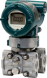
EJA110E
Differenzdruckmessumformer der EJA-E-Reihe mit traditioneller Montageart
-
EJA115E
Relativdruckmessumformer der EJA-E-Serie mit integrierter Blende
-
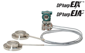
EJA118E
Differenzdruckmessumformer mit Druckmittlern basierend auf der EJA-E-Reihe.
-
EJA120E
Differenzdruckmessumformer der EJA-E-Serie für geringe Drücke mit traditioneller Montageart (IEC 61518)
-
EJA130E
Differenzdruckmessumformer der EJA-E-Reihe für hohe Drücke, mit traditioneller Montageart
-
EJA210E
Differenzdruckmessumformer der EJA-E-Reihe für Flüssigkeitsanwendungen mit Flanschmontage
-
EJA310E
Absolutdruckmessumformer der EJA-E-Serie mit traditioneller Montageart (IEC 61518)
-
EJA430E
Relativdruckmessumformer der EJA-E-Serie mit traditioneller Montageart
-
EJA438E
Relativdruckmessumformer mit Druckmittler der EJA-E-Serie
-
EJA440E
Hochleistungs-Relativdruckmessumformer der EJA-E-Serie mit traditioneller Montageart (IEC 61518)
-
EJA510E
Absolutdruckmessumformer der EJA-E-Serie mit Manometeranschluss
-
EJA530E
Relativdruckmessumformer der EJA-E-Serie mit Manometeranschluss
-
EJX110A
Differenzdruckmessumformer der EJX-A-Reihe mit traditioneller Montageart
-
EJX115A
Relativdruckmessumformer der EJX-A-Reihe mit integrierter Strömungsblende
-
EJX118A
Differenzdruckmessumformer mit Druckmittlern basierend auf der EJX-A-Reihe.
-
EJX120A
Differenzdruckmessumformer der EJX-A-Reihe für geringe Drücke, traditionelle Montageart
-
EJX130A
Differenzdruckmessumformer der EJX-A-Reihe für hohe Drücke, mit traditioneller Montageart
-
EJX210A
Differenzdruckmessumformer der EJX-A-Reihe für Flüssigkeitsanwendungen mit Flanschmontage
-
EJX310A
Absolutdruckmessumformer der EJX-A-Serie mit traditioneller Montageart
-
EJX430A
Relativdruckmessumformer der EJX-A-Serie mit traditioneller Montageart (IEC 61518)
-
EJX438A
Relativdruckmessumformer mit Druckmittler der EJX-A-Serie
-
EJX440A
Traditional-mount High Gauge Pressure Transmitter based on the EJX-A Series as a high performance model.
-
EJX510A
Absolutdruckmessumformer der EJX-A-Serie mit Manometeranschluss
-
EJX530A
Relativdruckmessumformer der EJX-A-Serie mit Manometeranschluss.
-
EJX610A
Hochleistungs-Absolutdruckmessumformer der EJX-A-Serie mit Manometeranschluss
-
EJX630A
High-End-Relativdruckmessumformer der EJX-A-Serie mit Manometeranschluss
-
EJX910A
Der Messumformer misst Differenzdruck, statischen Druck und Prozesstemperatur mit größter Genauigkeit und berechnet auf dieser Grundlage den Massenstrom, wobei der integrierte Hochleistungsdurchflussrechner voll kompensierte Werte liefert.
-
EJX930A
Dieser Messumformer wurde speziell für hohe statische Drücke entwickelt. Er misst Differenzdruck, statischen Druck und Prozesstemperatur mit größter Genauigkeit und berechnet auf dieser Grundlage den Massedurchfluss, wobei der leistungsstarke, integrierte Durchflussrechner voll kompensierte Werte liefert.
-
EJXC40A (DRS)
Beim DRS-Messumformer werden zwei Drucksensoren verbunden: Master (Hochdruckseite) und Slave (Niederdruckseite) an einem Remote-Standort in Kombination einem dedizierten DRS-Kommunikationskabel zur Messung des Differenzdrucks.
-
EJXC50A, EJAC50E (direktmontierter Druckmittler für Relativdruck)
Das direkt montierte Druckmittlersystem besteht aus einem Relativdruckmessumformer mit einem einzigen direkt angeschlossenen Druckmittler.
-
EJXC80A, EJAC80E (Direktmontierter Druckmittler für Differenzdruck)
Das direktmontierte Druckmittlersystem besteht aus einem Differenzdruckmessumformer mit einem einzigen direkt angeschlossenen Druckmittler.
-
EJXC80A, EJAC80E (Membrandruckmittler für Differenz-/Relativdruck)
Das Druckmittlersystem besteht aus einem Relativdruck- oder Differenzdruckmessumformer mit ein oder zwei Membrandruckmittlern.
-
EJXC81A, EJAC81E (Membrandruckmittler für Absolutdruck)
Das Druckmittlersystem für Absolutdruck besteht aus einem Absolutdruckmessumformer mit einem einzigen Membrandruckmittler.
-
Füllstand
Genaue Messungen sind eine entscheidende Voraussetzung, damit Ihre Anlage sicher, zuverlässig und gewinnbringend läuft. Füllstandsmessumformer messen den Differenzdruck und ermitteln anhand des Ergebnisses den Füllstand eines Behälters.
-
Geringer Druck
Um geringe Druckunterschiede bei sehr niedrigen statischen Druckverhältnissen zu messen, werden spezielle Differenzdruckmessumformer für geringe Drücke eingesetzt.
-
Hygienic Pressure Transmitters
Hygienic Pressure Transmitters are designed to fulfil the requirements of hygienic and pharmaceutical application.
-
Massedurchfluss (multivariabel)
Der Markt bietet verschiedene Verfahren zur Bestimmung des Massedurchflusses. Eine davon ist der multivariable Druckmessumformer.
-
Niedrigdurchfluss
Intelligente Differenzdruckmessumformer können mithilfe der Bernoulli'schen Gleichung bestimmen, wieviel Flüssigkeit durch eine Leitung fließt.
-
Relativdruck
Relativdruckmessumformer messen den Druck im Verhältnis zum Atmosphärendruck.