FU24 – General Comments
The FU24 was originally developed for harsh chemical applic ations were large temperature/pressure variations results in early depletion of the sensors reference chamber, subsequent signal drift and finally loss of functionality.
Designed with an internal bellow, large reference chamber and long-life reference probe, the expected sensor life time was calculated to be about 20 years at 20° C in demineralized water.
Further lab tests (D&E 2010-015 & D&E 2011-020) and fiel d tests (D&E 2012-022) indicate that the FU24 also performs very well in pure water applications. Results have been complied below into one document.
Lab Test – FU24 in Pure Water Application
Purpose / Summary
The purpose of this is to describe the test measurem ents made in pure water with the FU24. By comparison SR20-AC32 (Bellomatic) / AM21-AG2 or AL4 dual sensor systems were used as reference. The following tests are reported:
- 2 hrs test in demineralized water (~1 μ S/cm).
- 5 hrs test with demineralized water (~1 μ S/cm) and ultra-pure water ((~0.1-0.4 μ S/cm).
- 5 wks test with ultrapure water (~50-200 nS/cm).
All tests were at ambient temperature (about 20°C), and a flow rate of about 100 ml/min.
Conclusions
- The main conclusion is that in the reported tests, the FU24 performed as good as the reference system using a separate Bellomatic + glass electrode system.
- Based on the KCl diffusion rate, at 20°C a life time of the FU24 reference chamber of about 20 years is calculated.
Procedure
Test Set-up #1
The sensor is placed in a vessel filled with water. A reference sensor combination (SR20-AC32 + SM21-AG2) is placed in a second vessel. A water source (tap-, demineral ized- or ultrapure water) is split, to flow through both vessels at a rate of 100 ml/min. Then behind both test vessels an FF40 flow fitting is placed with an SC41-SP34 conductivity sensor to monitor the flowing water co nductivity. The pH and cond uctivity measurements are monitored continuously for the duration of the test.
 |
| Figure 1: Low Conductivity Water Test Set-Up #1 |
Test Set-up #2
Essentially it was the same set-up as Test Set-up #1, but with one Test pot only for maximum 5 sensors. There was one FF40 flow fitting with an SC41-SP34 in the water in let to monitor the conductiv ity of the feed water, and another FF40 flow fitting with an SC41-SP34 in the outlet to monitor the conductivity of the effluent from the Test pot.
 |
| Figure 2: Low Conductivity Water Test Set-Up #2 |
Results and Discussion
The water sources used in the Short term tests, using Test set-up #1, had the following conductivities:
| Tap Water: | about 250 μ S/cm Demineralized |
| Water: | about 1 μ S/cm |
| Ultra-Pure Water: | about 0.1 μ S/cm |
The pH-sensors used in the reported tests were not calibrated. The absolute values therefore cannot be compared. However the main focus is on the stability of the signal not the absolute mV and/or pH readings.
Test #1:
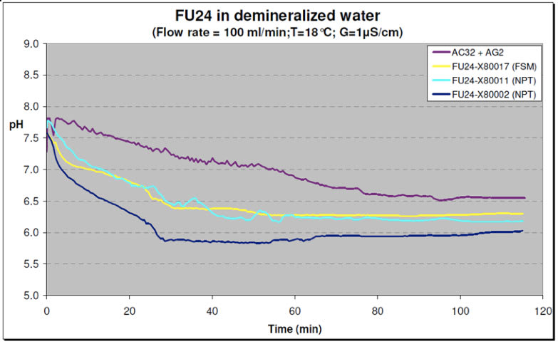
In one test, using Test Setup1, the Vessels were filled with tap water and flushed with demineralized water (see Figures 3& 4). The conductivity was recorded at various time intervals. After about 40 minutes the conductivity in the test vessel with FU24 sensors was stabilized at about 1 μ S/cm. The test vessel with the reference SR20-AC32 + SM21-AG2 sensors took a little longer because of the larger volume (less and smaller sensors). The FU24 sensors demonstrated a steady regular signal pattern comparable to the reference sensor system.
 |
| Figure 3: Test with Demineralized Water – mV signal |
 |
| Figure 4: Test with Demineralized Water – pH |
Test #2:
In another test, using Test Setup #1, the vessels were filled with demineralized wa ter. After about 2 hours a switch was made to flush with ultra-pure water (see Fi gure 5) for another 3 hours. Both the SR20-AC32 + SM21- AG2 reference sensor system and the FU24 sensors showed a more fluctuating signal in Ultra-Pure Water as in demineralized water. These fluctuations are in t he order of about 10 mV or 0.2 pH units (min-max).
 |
| Figure 5: Test with Ultra-Pure Water – pH |
Test #3:
In order to confirm possible application of the FU24 in pure water applications, a longer term test was performed using Test Set-up2. A Behropur B5 demineralization unit wa s used to purify the tap water supply to the Test pot. The conductivity of the inlet water was reduced to 40 -50 nS/cm. An SR2-AC32/SM21-AL4 reference combination was placed in the Test pot together with 2 FU24 sensors. A flow rate of 100 ml/min was maintained for about 5 weeks while the conductivity, temper ature and mV/pH values were continuo usly monitored. The conductivity and pH data are shown in Figure 6. The mixed bed ion exchanger in the de mineralization unit had to be replaced a bout every 4-5 days. As the full ion exchange capacity of the bed was reached, not only the conductivity of the water increased but the pH also changed. The decrease in pH is most likely caused by an imbalance in the ratio of anionic/cationic resin of the mixed bed ion exchanger. This turned out to be a good cont rol feature, because it helped to observe the response of the sensors to pH changes in low condu ctive water.
 |
| Figure 6: Test with Ultra-Pure Water – pH & Conductivity measurements during 5 weeks |
 |
| Figure 7: Flowing 50 nS/cm water thru a testpot with one SR20-AC32 and two FU24 sensors |
The conductivity of the water coming out of the test pot was in the range of 100 – 200 nS/cm. The temperature varied between 16 – 21°C. The pH data plotted in Figure 6 was corrected to a constant temperature of 20°C. The graph shows 10 points moving average trend lines. Part of the variations in the conductivity is caused by the non- steady flow rate of the tap water supply. The actual flow rate was 100 ± 20 ml/min.
The data proves that the AC32/AL4 se nsor system and both FU24 sensors follow the system pH-changes in similar response. This is even more noteworthy, since the pH-probe glass surface area of the FU24 is about 60% of the surface area of the refe rence SM21-AL4 glass sensor. The main factor in pure water applications is the low conductivity resulting in a large resistance bet ween the reference and the glass electrode. In the FU24 sensor the diaphragm of the reference electrode is in near proximity of the glass electrode compared to a separate AC32 – glass electrode system. The fact that the resistance is reversed proportional to the distance is in favor for the FU24. The internal overpressure of the FU24 caused by the bellow, might also favorably help diffusion out of the sensor comp ared to other combined sensors.
De pattern of sensor FU24 – A1-0023 shows a shift in pH levels after the first two changes of the ion exchange resin beds. Apparently t here was some dirt on the gla ss that was washed away during the 'acid' flushes at end of the ion exchanger bed life time. This has no rela tion to the effect of the pure water itself.
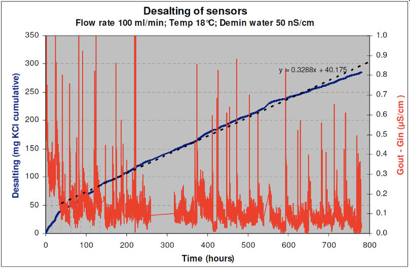
The red line in the graph shows the difference inconductivity between inlet and outlet of the test pot. The spikes observed are most likely electronic noise effects. The irre gularities and wave patterns are attributed to fluctuations in the actual flow rate and the ambient temperature. The temperature was found to vary between 16 – 21°C in a more or less steady, weekly pattern.
The conductivity values recorded during the 5 weeks test were used to calculate the KCl release rate. The desalting rate is shown in Figure 6 where the cumulative amount of KCl diffused out of the sensors is plotted in time. With the coëfficients of the regression line it is calculated that the FU24 KCl supply is depleted after 20 years under these conditions.
During the first week, the conductivity increase caused by flow and diffusion of KCl out of the sensors, was on average about 141 nS/cm. In a control test an SR-AC32 & SM21-AL4 were placed in the Test pot, without any other sensor present. The average increase in conducti vity caused by the flow of the Bellomatic was about 35 nS/cm. This means that the two FU24-s ensors contributed about 53 nS/cm each.
Based on the available data an average life time of the FU24 reference chamber is calculated at 20°C:
Life time = WKCl / (GFU24 / ((SGCl- + SGK+)*MKCl* f * 60 * 24 * 1000 * 7 * 52)) – years
| = 20 years | |||
|---|---|---|---|
| f | (Avg Flow rate) | 100 | ml/min |
| GFU24 | (Conductivity from FU24) | 0.053 | μS/cm |
| WKCl | (Avg amount of KCl in FU24) | 28 | g |
| SGCl- | (Specific conductivity Cl-) | 76300 | mS.cm2/mole |
| SGK+ | (Specific conductivity K+) | 73500 | mS.cm2/mole |
| MKCl | (Molar mass KCl) | 74.4 | g/mole |
| US field test – FU24 in pure water application | |
|---|---|
| Model: | FU24-VP-T1-NPT |
| Serial No.: | A1-0020 |
| Process: | UPW application. The probes are installed on the hot well, deaerator inlet and economizer., pH 8.2 to 8.8., conductivity .06 μs/cm. Flow 1.5-2.0 gph (appr. 5.5–7.5 l/hr). Temperature: 28°C; ambient Pressure. pH is checked 2 times per week using a bench top. |
| Maintenance: | Buffer calibrations once per month with buffer pH7 & pH9, where slopes are recorded. |
| In service: | 12.5 months. Precautionary replaced by Service engineer.. |
| Analysis: | The lab results on returned sensor show: |
| Aspot: -3.4 mV | |
| Slope: 97.3% | |
| Ref Pot.: 44.3 mV | |
| Diaphragm res.: 5.8 kOhm | |
| Glass res.: 390 MOhm | |
| Visual: Bellow is still in tension. | |
| Overall conclusion is that the sensor is still fully functional and not near its life end. Replacement was not justified. | |
Customer comments: Customer likes the FU24 because it has No maintenance, compared to the Bellomatic (SR20-AC32). They like the FU24 so much, they are budget ing to replace 12 Bellomatic s systems that are less than 5 years in service. This is due to maintenance time spent refilling and servicing the Bellomatic.
 |
|
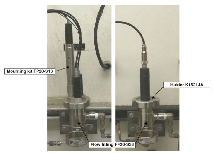
Pictures 1 & 2: 3-Sensor system (pH + Bellomatic Ref + Temp) |