Introduction
Process plants making pH measurements expect accurate, reliable performance with a reasonable electrode life expectancy while minimizing maintenance. A quality pH sensor system, when undamaged, cleaned, and properly calibrated, will provide such performance.
However, an electrode — even in a process that does not cause coating, plugging, abrasion, or any other problems — still requires periodic calibration to correct for sensor aging and non-recoverable changes to the electrode. Since these aging effects happen slowly, calibration should not be required more often than once a month in typical general-purpose applications. The need for more frequent calibration stems from a specific cause, i.e.:
- an aggressive process;
- ineffective electrode cleaning;
- improper routine calibration;
- overly temperature-dependent pH; or
- incorrect electrode selection.
Dirty or faulty electrodes can cause anything from slow response to a completely erroneous reading. For example, if a film remains on the pH sensor after cleaning, the resulting measurement error could be misinterpreted as a need for re-calibration. Correct cleaning can reverse these changes and is a key maintenance step.
The accuracy of pH measurements depends upon maintenance; maintenance frequency largely depends upon the application. Understanding and addressing the causes of pH measurement difficulties comprise key to ensuring stable and accurate readings. However, troubleshooting a pH system can pose challenges. The guidelines presented here are a good starting point for tackling problems.
Insights from Calibration
Troubleshooting has four main parameters:
- asymmetry/zero;
- slope;
- measuring electrode impedance; and
- reference electrode impedance.
Most commercial instruments provide asymmetry/zero and slope readings. A pH system with a solution ground/liquid ground and advanced sensor diagnostics also will provide impedance values. Understanding the purpose of each of these values indicates where problems lurk — and where to start your search for answers.
The asymmetry potential (AS), also referred to as the millivolt offset, indicates the condition of the reference electrode. Theoretically, when the electrodes are placed in a pH-7 buffer solution, the millivolt output from the electrode pair (pH and reference) should be zero. An asymmetry reading of 20 means the pH sensor is generating 20 mV instead of the expected 0 mV.
The reference sensor causes most asymmetry problems. Some millivolt offsets stem from potassium chloride (KCl) depletion from the reference electrolyte or poisoning of the reference electrolyte with process solution. When the offset is ±30 mV or more, the reference electrode should be replaced. Per the Nernst equation, a change in pH of 1 results in 59.16 mV at 25°C. If the pH system has 30 mV of offset, the adjustment for an incorrect reading is equal to 0.5 pH.
The slope, also referred to as the efficiency of the electrode, is an indication of the condition of the measuring (glass) electrode. The slope is given as a percentage value, with 100% being ideal. A new electrode should have a slope in the upper-90% range.
As the electrode ages and loses efficiency, the slope and response will start to decrease.
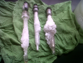
The slope value is updated each time a two-point calibration is performed; only small value changes should be visible. (Table 1 lists slope reading issues and actions.) Inadequate cleaning can lead to a coating buildup (Figure 1) that causes a low slope value; to avoid this, clean the electrode as needed with a 5–10% HCl solution for a minute, rinse thoroughly with clean water, soak and recalibrate. Replace the pH electrode when the slope value is in the mid-to low-80% range.
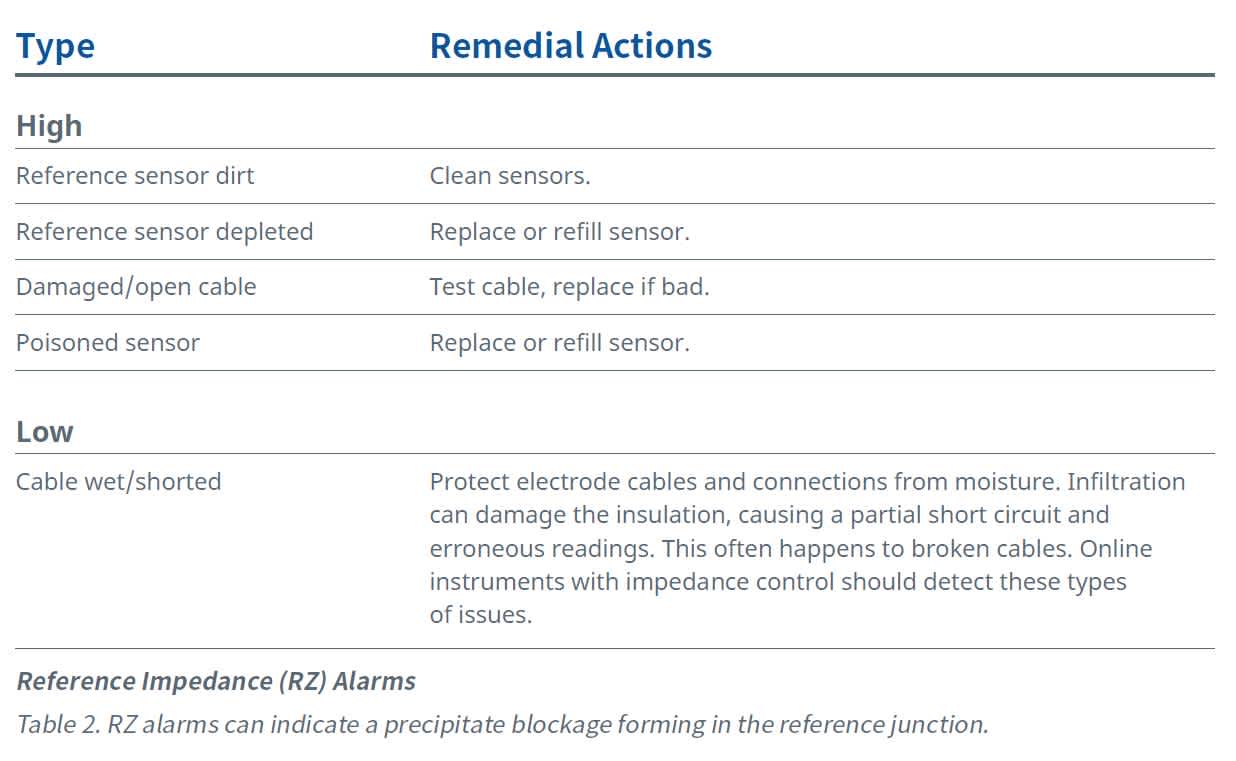
Readings from the reference impedance (RZ), also referred to as the resistance or the reference junction, can indicate the need to clean out a precipitate blockage forming in the reference junction. (Table 2 lists the causes and remedial actions for RZ alarms.) The conductivity of the process solution also influences this resistance.
Typically, a clean reference junction will have a resistance of less than 10–15 kΩ but, in low conductivity solutions, RZ values between 200 kΩ and 500 kΩ aren’t uncommon. When the RZ value starts to approach 30–35 kΩ, the electrode will begin a slow upward drift. When the reference impedance exceeds 100 kΩ, an error message should appear on the instrument connected to the pH sensor.
Some instrumentation also will provide a measuring glass impedance value and corresponding alarms. (Table 3 lists the causes and remedial actions for electrode impedance alarms.) These alarms typically serve to indicate faulty equipment.
Common Problems and Remedies
Once a system is calibrated and functioning properly, problems can still creep into an application. Following are common examples, along with corresponding solutions.
Improper cable preparation. Use a cable with the correct length. Attempting to cut a longer cable could cause errors. To prevent inside radiation or disturbances, a cable includes a special layer of graphite for screening. Removing this layer is very difficult. Measurement errors and instability commonly turn up in a shortened cable due to a severe loss of isolation resistance between its core and screen. For a glass electrode cable, this isolation resistance must exceed 1,000 times the resistance across the glass membrane.
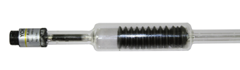
Drifting. Over time, a probe’s reading may drift up or down. As the asymmetry potential (mV offset) becomes greater, the electrode will drift and require more frequent calibration. A common cause is the depletion of KCl from the reference electrolyte. This generally happens when a gel-filled reference electrode is used in the wrong process solution, such as high-purity water. When the concentrated reference electrolyte (KCl) and the low conductivity (mineral-free) process solution meet at the reference junction, the process solution leaches salt from the reference electrolyte, causing the reference potential to become unstable (Figure 2).
Another cause of drift is poisoning of the reference electrolyte with the process solution. This is most common in applications with process pressure greater than 1 atm. The process pressure overcomes the pressure inside the electrode, forcing process solution into the reference electrode and contaminating the electrolyte. This increases the millivolt offset; replace the reference electrode when the offset value is ±30 mV or more.
Process solutions containing sulfides or sulfur-bearing species can cause drifting by reacting with the silver chloride in the reference electrolyte, prompting formation of insoluble precipitates in the reference junction. These precipitates result in high electrical junction resistance, which leads to nonreproducible diffusion potentials, causing the electrode to have a slow constant upward drift. When the RZ value begins to approach 30–45 kΩ, the electrode will start a slow upward drift.
Noisy readings. Since it is open to the process via the junction, the reference electrode is the weakest link in the measurement loop; it is very susceptible to the interference of stray voltages in the liquid. In many applications, the voltage potential of the process liquids is significant and cannot be neglected when making pH measurements. Therefore, the technician must ground the liquids at the point where the pH value is to be measured, usually by using metal fittings or plastic fittings with a grounding (solution ground) electrode of suitable metal.
One way to test if stray voltages are causing errors is to take the pH system offline and place the sensor in a process grab sample. If the sample reading is stable but drifts when placed online, there are stray voltages. Another test is to install a jumper in the instrument between the reference and the solution ground terminals. If the reading locks in place, a stray voltage problem exists.
Slow response time. Sluggish performance indicates coating or plugging of the junction, which can be caused by a thin film invisible to the naked eye on the glass sensor.

A variety of cleaning solutions can remove a coating. However, a 5–10% solution of HCl usually works well. Follow these steps:
- Rinse the sensor in plain water to remove any heavy process coating.
- Immerse the electrodes in the cleaning solution for one to two minutes, agitating them regularly.
- Use a soft brush to clean off coating deposits, taking care not to damage the electrodes.
- Rinse the electrodes thoroughly with clean water to avoid contamination of the calibration buffers.
- Soak for two to three minutes in water.
As the electrode ages and loses efficiency, response time slows and the slope value decreases. As already noted, a low slope value indicates improper cleaning before calibration.
The pH measurement is wrong online but correct in buffers. This common problem is called diffusion potential. If the sensor junction is plugged, the electrical contact between electrolyte and process is poor, and diffusion potential is measured directly as an error. The chemical composition of a pH buffer differs from that of the process liquid; therefore, when the junction is in bad condition, this error is calibrated in the pH buffer solution but varies for the process solution. An easy check is to look at the diagnostic information in the pH instrument.
High asymmetry potential or low slope indicates this problem. Ground loop current caused by a pH sensor without proper solution grounding also can be the culprit.
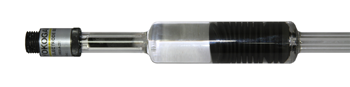
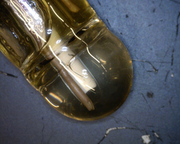
Cracked membranes. A minute invisible crack in the membrane of a glass electrode, often caused by frequent temperature shocks, can cause measurement errors. For example, if an instrument reads 0 mV it will show pH 7, but if the sensor is placed in a buffer with pH 4, the instrument still will read pH 7. For neutralization processes where the set point typically is pH 7, this is very critical and a dangerous situation. Without additional diagnostic checks, the error will remain undetected. Those pH systems with a solution ground and online impedance-sensor diagnostics frequently monitor the impedance of the pH membrane via the solution ground, and will generate an alarm in the case of a broken glass membrane (Figure 3).
Dry electrodes. When a pH electrode dries out in storage or in a process, its performance suffers. The pH reading may become slow and erratic and can shift upscale, resulting in a shortened span. A dry pH electrode possibly can have its gel layer rejuvenated. Short exposures to dry conditions caused by calibration, troubleshooting routines or a batch refill of a process tank usually require no extra handling to regain a fully functioning electrode.
The user can treat longer exposures, such as being uncovered in an empty tank or sitting on a bench for 12 hours or more, in several ways. The first is to soak the electrode in a 4.0-pH or 7.0-pH buffer solution, a reference fill solution or tap water. The length of soaking depends upon how long the electrode was left dry; soaking typically lasts 30 minutes for short dry periods and to 24 hours for more severe instances. Alternatively, place the electrode into service immediately with the understanding that some measurement uncertainly will exist until the electrode recovers. During this recovery period, a pH calibration will be marginally helpful. Since the gel layer is changing with exposure to process fluids, to achieve best accuracy, a second calibration must be performed within eight to 24 hours. Typically, heating dried-out sensors to 80°C in electrolyte and then allowing them to cool to room temperature will restore them.
- Laboratory and process measurements don’t match. When this happens, the normal inclination is to consider the inline measurement to be incorrect. The actual fault can be determined by following this procedure:
- An accuracy of ±0.1 pH for each instrument normally is acceptable, with further troubleshooting only required when the total uncertainly exceeds ± 0.2 pH.
- Are both instruments accurate? Validate each by measuring two or three fresh buffer solutions.
- Do not make any adjustment. Record the values and judge the results. If one is wrong by 0.1 pH or more, calibrate it and repeat the test.
- Compare “apples with apples” by ensuring the inline and the laboratory instruments are measuring the same sample at the same pressure and temperature. Do not measure in the lab at reference temperature when the inline measurement is at process temperature. Compensate the inline instrument temperature by taking a hot sample, inserting the sensor and letting it cool to 25°C. The reading should become stable if there is proper temperature compensation. If the reading changes, calculate the Δ pH/Δ temperature, and program this coefficient into the instrument if possible.
- Consider the process properties. For example, with boiler feedwater, the process solution will be ultrapure water with traces of ammonia or morpholine that increase the pH. As soon as the sensor is exposed to ambient air, the pH will drop due to absorption of atmospheric carbon dioxide.
Start with the Reference Electrode
When troubleshooting, remember that the reference electrode accounts for 80% of all typical pH-measurement problems. As discussed, the main issues are:
- Process solution enters through the diaphragm or junction and poisons the Ag/AgCl element or electrolyte.
- The diaphragm/junction becomes coated or plugged.
- The internal electrolyte (KCl solution) becomes depleted.
These all undermine the proper operation of the reference electrode, causing instability and inaccuracy. Most problems can be solved through basic maintenance:
- Coating of the glass membrane (sluggish readings): Clean the membrane.
- Coating or plugging of reference junction (open circuit): Perform cleaning or use polytetrafluoroethylene junctions so particles do not adhere. Positive pressure and a flowing reference will help prevent coating and plugging.
- High resistance between electrodes (pure water or an open circuit): Ensure the flowing reference provides enough KCl ions to achieve a conductive path between the reference and glass electrode to complete the measuring circuit.
- Pressure spikes drive process solution into the reference electrode, forcing out electrolyte and causing a change in KCl concentration and a loss of a stable reference voltage: One way to combat this is to use a reference system having a flowing junction type that maintains a constant flow of electrolyte out of the sensor at all times.
- Some ions (e.g., sulfides, cyanides, and bromides) react with Ag+ to form silver sulfide, which deposits in or on the junction, plugging it and attacking the internal reference pin: A double-junction-style reference can delay this poisoning or a positive-pressure version of the sensor can prevent the
- poisonous ions from migrating into the reference.
Ultimately, poisoning of the Ag/AgCl element, plugging of the junction, and depletion of internal KCl solution all are key measurement concerns to address. The effects of these problems can be reduced by increasing maintenance, including the frequency of cleaning and calibrating the electrodes, as dictated by the aggressiveness of the process.

Related Industries
-
Chemical
Chemical plants rely on continuous and batch production processes, each posing different requirements for a control system. A continuous process calls for a robust and stable control system that will not fail and cause the shutdown of a production line, whereas the emphasis with a batch process is on having a control system that allows great flexibility in making adjustments to formulas, procedures, and the like. Both kinds of systems need to be managed in available quality history of product, and to be able to execute non-routine operations. With its extensive product portfolio, experienced systems engineers, and global sales and service network, Yokogawa has a solution for every plant process.
Related Products & Solutions
-
SENCOM™ SMART Digital Sensors
Reduce configuration time and simplify maintenance
-
pH and ORP Analyzers
Optimize field maintenance, calibration, and system configuration
-
pH and ORP Sensors
Ensure fluid process operations
Have Questions?
Contact a Yokogawa Expert to learn how we can help you solve your challenges.