


The Data Logger that can be used flexibly according to the equipment
Industrial processes often employ multiple data acquisition systems to monitor the health of assets and facility infrastructure. These systems can be either standalone or built as nodes within a larger automation topology.
The GM10 is a scalable modular block I/O data acquisition system and data-logging platform that is designed for easy installation and maintenance and requires no programming. It supports remote web-based or wireless configuration and monitoring via Bluetooth connection. The unit can be DIN rail mounted, wall mounted or act as a standalone desktop application. The Yokogawa GM10 delivers industry leading reliability and measurement accuracy. In addition, a wide range of communication protocols guarantee compatibility with your network architecture.
> Added the “Elapsed time calculation” function to easily measure operating time and processing time
> Added the “F value calculation” function required for the sterilization process
Easier to use and more convenient
Industry's first! AI Equipment / Quality Easy Predictive Detection
Equipment/Quality Easy Predictive Detection:
By easily creating predictive detection models from past recorded data, you can detect prediction of abnormalities in manufacturing equipment and products at an early stage.
> Click here for details on AI Predictive Detection
> AI related products : go to AI Product Solutions page

Supports the aerospace industry's AMS2750/NADCAP and the automotive industry's CQI-9 for heat treatment applications (option)
Schedule management for periodically executing calibration correction configuration and the like. Compliant with heat treatment standard CQI-9 adopted by major companies in the automotive industry.
> Heat treatment special site
Supporting FDA 21 CFR Part 11, EU-GMP Annex 11, and data integrity

The advanced security function provides safety to use. With the expansion of the advanced security function option (/AS), it corresponds to US FDA 21 CFR Part 11, EU-GMP Annex 11, and data integrity in accordance with ALCOA +.
> What is "ALCOA +"?
Download technical data:
Regarding analog measurement, we have summarized the frequently asked questions in [Basic], [Applied], and [Noise Countermeasures]. > Download
About OpreX
OpreX is the comprehensive brand for Yokogawa’s industrial automation (IA) and control business and stands for excellence in the related technology and solutions. It consists of categories and families under each category. This product belongs to the OpreX Data Acquisition family that is aligned under the OpreX Measurement category.
Details
Predictive monitoring with AI
Equipment/Quality Easy Predictive Detection
* Creating predictive detection models and profile waveforms requires the Equipment/Quality Predictive Detection tool (sold separately).
Easily determine the quality of processes and equipment with the Health Monitor function
By easily creating predictive detection models from past recorded OK/NG (Not Good) data and loading it into GM, you can detect prediction of abnormalities in manufacturing equipment and product quality degradation at an early stage. And because health scores which show the degree of normal and abnormal data consider correlations among multiple data to make determinations, they can capture prediction of abnormalities that are difficult for humans to detect.
- Maximum number of channels: 20
- Shortest recording interval: 100 ms
- Target channels: I/O channel, math channel, and communication channel
- Files that can be used to create a predictive detection model:
[Yokogawa products] SMARTDAC+, DXAdvanced
[Other companies’ products] KEYENCE : TR-W1000 and TR-W500 csv file, CHINO : KR2000 and KR3000 csv file, EUROTHERM : 6100A and 6180A csv file

Health monitor function empowers you to:
- Perform maintenance and repair before equipment malfunctions and product quality degradation
- Quantify degrees of equipment deterioration and quality degradation
- Easily build equipment/quality predictive detection systems on site

Profile function delivers real-time warnings of abnormalities
By creating a profile waveform from past recorded data and loading it into GM, this waveform can be used as a threshold for process values. Profile waveforms are useful in applications where process values change over time. Also, you can see the deviation from the reference waveform on the screen.
- Maximum number of channels: 20
- Shortest recording interval: 500 ms */MC option required

Profile function empowers you to:
- Monitor and set alarms for the entire process, including the initial rise
- Compare the current process values with the ideal waveform

Please refer to the application notes for the proven effects and use cases of predictive detection.


Free trial for 60 days!* Equipment/Quality Easy Predictive Detection
By creating predictive detection model and profile waveform, Cloud or Offline Equipment/Quality Predictive Detection tool (paid separately) is required. To use cloud version, you need to apply from the following site to create an account.
*There are some functional restrictions during the free trial period.
- Cloud version : Predictive detection model cannot be loaded on SMARTDAC + main unit. It is possible to load the profile waveform into the SMARTDAC + main unit.
- Offline version : Neither of the sign detection model profile waveforms can be loaded into the SMARTDAC + main unit.
> Click here to apply for the cloud version
> Click here to download the offline version
*Search "OE10" on the member's site.
Note: Cloud version is available only for US, Canada, EU and UK.
MATH (including reports), and event actions
MATH function (/MT option)
Supports various kinds of math computation, including basic math and functions (square root, logarithms, F value, elapsed time, etc.). Elapsed time calculation allows you to measure the amount of time elapsed after a condition is met.
Write formulas using variables for measured or computed data and save or display the results―this saves time and effort on post-processing. Create hourly, daily, monthly, and other reports with the Report function.

Event actions
Ability to assign actions tied to specific events during the operation of the data acquisition station.

Elapsed time calculation
Elapsed time calculation allows you to measure the amount of time elapsed after a condition is met. The measured time can be recorded through math channels.
F-value calculation
F-value calculation allows you to measure the lethal value of bacteria. The measured value can be recorded through math channels.

Data analysis made simple and mobile
High speed measurement (down to 1 ms)
Yokogawa's proprietary A/D converter allows the high speed module to measure data points as fast 1ms.
- High speed (1 ms) measurement*
- Proprietary A/D converter
*With 1ch per module. At 2 ms, 2 ch per module, and at 5 ms or more, all 4 ch per module.
| Model | Scan interval | ||
|---|---|---|---|
| 1ms | 2ms | 10ms | |
| GM10-1 | 1ch | 5ch | 10ch |
| GM10-2 | 5ch | 25ch | 32ch |

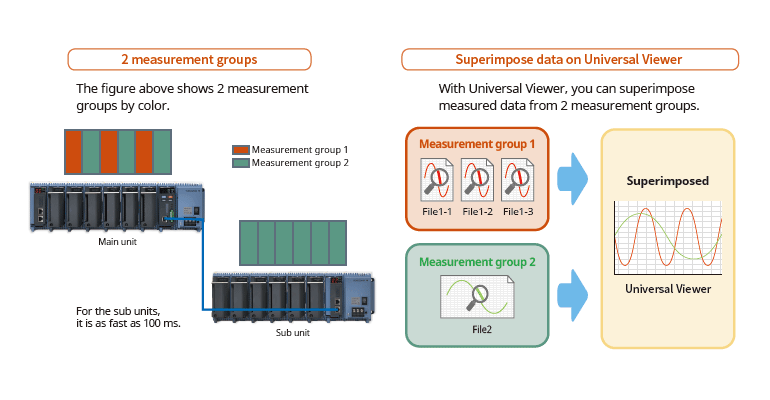
Dual interval measurement with two different scan intervals
Users have the ability to choose two different scan intervals on a single GM system. This allows users the flexibility to measure various types of inputs with two different scan intervals in a single system. For example, this provides for efficient, simultaneous measurement of signals with slow fluctuations such as temperature, and fast-changing signals such as pressure and vibration. Modules can be assigned to measurement groups.
PID control function
Control function to enable PID and program control
- PID control module
2-loops per module, up to 20 loops per system - Setpoint program control function (/PG option)
Up to 99 patterns

Remote operation and monitoring
The web application enables remote operation and monitoring from a browser.

Supports the aerospace industry's AMS2750/NADCAP and the automotive industry's CQI-9 for heat treatment applications
Calibration correction schedule control function (/AH option)
Schedule management for periodically executing calibration correction configuration and the like. You can set the input correction factor as a sensor correction factor and instrument correction factor. For AMS2750, we offer TUS software* that can easily create TUS (temperature distribution test) reports.*
* For details on TUS software, consult with your Yokogawa dealer.

Input calibration is performed in the AI channel setting screen, and the calibration period settings are entered in the schedule management setting screen.
Record data in separate files per equipment set
Multi-batch Function (/BT option)
Record pre-defined channel groups to separate data files with independent start and stop control. You can create up to 12 batches.

Automatically create reports with any template
Report creation and network functions (/MT option)

Ready for the future when you are, Smart Architecture
Increase channels by adding additional block modules
- Expand one, or multiple module at a time
- Unique design houses modules in linked module bases
- Module base ensures linkage (slide locks and mounting screws also available)
- Modules can be inserted and removed from the front panel for easy maintenance

Names of data acquisition module parts

Comes standard with support for up to 100 ch of measurement (single-unit configuration)
Up to 10 I/O modules can be linked to a single data acquisition module (GM10)

Installs anywhere

Select from a wide range of I/O modules
Select modules according to your application. Noise-resistant, magnetic relay types also available. All modules have removable terminal blocks for easy wiring. The same modules used in the SMARTDAC+TM series.

| Model | Name | Measurement/Application | Channels |
|---|---|---|---|
| GX90XA-10-U2 | Analog input module | DC voltage, DC current (with external shunt resistor connected), thermocouple, RTD, contact (solid state relay scanner type) | 10 |
| GX90XA-10-L1 | DC voltage, DC current (with external shunt resistor connected), thermocouple, contact (Low withstand voltage solid state relay scanner type) | 10 | |
| GX90XA-10-T1 | DC voltage, DC current (with external shunt resistor connected), thermocouple, contact (electromagnetic relay scanner type) | 10 | |
| GX90XA-10-C1 | DC current (mA) (solid state relay scanner type) | 10 | |
| GX90XA-10-V1 | DC voltage, DC current (with external shunt resistor connected), thermocouple, contact (Solid state relay scanner type) | 10 | |
| GX90XA-04-H0 | DC voltage, DC current (with external shunt resistor connected), thermocouple, RTD, contact (individual A/D type) | 4 | |
| GX90XA-06-R1 | 4-wire RTD, 4-wire resistance(solid state relay scanner type) | 6 | |
| GX90YA | Analog output module | Current output (isolated between channels) | 4 |
| GX90XD | Digital input module | Remote control input or operation recording | 16 |
| GX90YD | Digital output module | Alarm output | 6 |
| GX90WD | Digital input/output module | Remote control input or operation recording/alarm output | DI:8/DO:6 |
| GX90XP | Pulse input module | Pulse signal data acquisition, integral count | 10 |
| GX90UT | PID control module | PID control (2 loop) | AI:2/AO:2 DI:8/DO:8 |
* For details on each module, refer to the general specifications.
You can also select modules using the convenient selection tool Product Finder.
Analog input module scan interval and measurement type
| Type | Channels | Scan interval (shortest) |
Scanner | TC | RTD | DCV | DI | mA | Resistance | Feature |
|---|---|---|---|---|---|---|---|---|---|---|
| Universal (-U2) | 10 | 100ms | SSR | √ | √ | √ | √ | Universal | ||
| Low withstand voltage relay (-L1) | 10 | 500ms | SSR | √ | √ | √ | Mid-price | |||
| Electromagnetic relay (-T1) | 10 | 1s | Relay | √ | √ | √ | Noise-resistance | |||
| DC current input (-C1) | 10 | 100ms | SSR | √ | mA only | |||||
| High withstand voltage (-V1) | 10 | 100ms | SSR | √ | √ | √ | High withstand voltage | |||
| High speed universal (-H0) | 4 | 1ms | — | √ | √ | √ | √ | High speed measurement | ||
| 4-wire RTD (-R1) | 6 | 100ms | SSR | √ | √ | 4-wireRTD |
Internal memory and max. I/O channels
| Type | Internal memory | Max. input/output channels* | |
|---|---|---|---|
| GM10-1 | 500 MB | Single-unit configuration | 0 to 100 |
| Multi-unit configuration | 0 to 100 | ||
| GM10-2 | 1.2 GB | Single-unit configuration | 0 to 100 |
| Multi-unit configuration | 0 to 420 | ||
Actual values support high precision measurement
| Input type | Measuring accuracy*1 (typical value*2) | |
|---|---|---|
| DCV | 20 mV | ±(0.01% of reading + 5 μV) |
| 60 mV | ±(0.01 % of reading +5 μV) | |
| 6 V (1-5V) | ±(0.01% of reading + 2 mV) | |
| TC*3 | R, S | ±1.1 °C |
| B | ±1.5 °C | |
| K (-200.0 to 1370.0°C) | ± (0.01% of rdg +0.2°C for 0.0 to 1370.0°C; ± (0.15% of rdg +0.2°C) for -200.0 to 0.0°C | |
| K (-200.0 to 500.0°C) | ± 0.2°C for 0.0 to 500.0°C; ± (0.15% of rdg +0.2°C) for -200.0 to 0.0°C | |
| J | ± 0.2°C for 0.0 to 1100.0°C; ± (0.10% of rdg + 0.2°C) for -200.0 to 0.0°C | |
| T | ± 0.2°C for 0.0 to 400.0°C; ± (0.10% of rdg + 0.2°C) for -200.0 to 0.0°C | |
| N | ± (0.01% of rdg + 0.2°C) for 0.0 to 1300.0°C; ± (0.22% of rdg + 0.2°C) for -200.0 to 0.0°C | |
| RTD | Pt100 (-200.0 to 850.0°C) | ±(0.02% of rdg + 0.2°C ) |
| Pt100 (-150.00 to 150.00°C) | ±(0.02% of rdg + 0.16°C ) | |
Support measurement of up to 420 ch (actual input) by expanding channels across multiple units (multi-unit configuration)
Expand up to 420 ch by using the GX90EX expansion module. (GM10-2)
On the GM10-2 large capacity type, up to 1000 ch are available for recording when including MATH and communication channels. Connect units with LAN cables for dispersed installations.

You connect directly with a LAN cable without connecting through a hub or repeater.
* You can also connect a GX60 expansion unit.
Reduce wiring with distributed installation
When the data logger is installed offsite (away from the DUT), you can place the sub unit at the site and monitor data without the need for long-distance wiring of thermocouples and other sensors.

Navigate with ease, Smart User Interface
Easy access from a Web browser
Through a Web browser you can monitor the GM in real time and change settings. You can easily build a seamless, low-cost remote monitoring system with no additional software.
Real time monitoring
With the scroll bar, you can seamlessly scroll between past and current trends
*Notice on Java Plug-in running in Web browser for SMARTDAC+ series

Enter settings online with a web browser
The setting screen lets you copy AI channel settings and other information to Excel for editing. You can reimport the data into the setting screen after editing.

Trend, digital, and other real-time displays

Dedicated software (free download) is available for loading waveforms and GM settings
Universal viewer
Data files saved on the GM can be viewed and printed. You can perform statistical computation over an area and export to ASCII, Excel, or other formats.

Offline setting software
Save settings or transfer them to the GM. Connections can also be made easily via USB or Bluetooth.

Safe to use in a wide range of temperatures
With operating temperatures of -20 °C to 60 °C, it supports a wide range of applications without concern about the installation environment.

Monitoring and settings can also be done on a tablet
Supports Bluetooth (optional code /C8)
You can enter settings or monitor from a tablet without ever bringing a PC to the site. Dedicated applications is available for free download. For more information, visit our website.
Enables monitoring via Bluetooth
Bluetooth supports Android only.

Enables monitoring via Wi-Fi
Wi-Fi supports both Android and iOS.

Powerful applications
Bluetooth connection
Simple to use for in-vehicle testing.

USB connection
Service staff can easily perform maintenance on the GM.

Provides a variety of convenient networking functions
Modbus/TCP and Modbus/RTU Communications
GM supports Modbus TCP/IP client and server modes for Ethernet communications and Modbus/RTU master and slave modes for optional serial communications.
Modbus/TCP (Ethernet connection)
Using the Modbus/TCP and Modbus/RTU functions, you can display and save data from the server and slave devices on the GM.*
* Requires the communication channel (/MC option).

Modbus/RTU (RS-422/485 connection)
Using the Modbus/TCP and Modbus/RTU functions, you can acquire GM data from upstream devices.

(You can connect up to 16 Modbus/TCP servers, or up to 32 servers with the GM10-2.)
(You can connect up to 31 Modbus/RTU slaves.)
EtherNet/IP Function (/E1 option)
Using the EtherNet/IP server function, you can access the GX from a PLC or other device to read measurement/computation channels and write to communication input channels (GX10: up to 500ch, GX20-1: up to 300ch, GX20-2: up to 500ch). Communication channel function (/ MC option) is required.
In addition, the following operations required for batch processes can be performed through the PLC using Explicit messages.
Note: Explicit message operation in OMRON PLC has not been confirmed.

PROFINET communication (GX90NW Network Module)
By using the GX90NW network module, you can connect the GM as a secondary I/O device via PROFINET. You can access the GM from the PLC or other I/O controller, read measurement/math channels, and write to communication channels*. You can easily perform necessary operations for batch processes from the PLC.
* Communication channel function (/MC option) is required.

Data acquisition on power measuring instruments (/E2 and /MC options)
Acquire precise digital data on the GM by digital communication connectivity to a power measuring instrument (WT series power analyzers) and record it along with the GM's measured data. Since it records a device's power consumption, temperature, and other phenomena at the same time, the GM is ideal for performance evaluation testing.
- Models that can be connected:
Yokogawa Test & Measurement Corp.,
WT1800/WT1800E (command type WT1800), WT500, WT300/WT300E (command mode WT300) - Max. no. of connections: 16

OPC-UA Server (/E3 option)
Data acquired by the GM can be accessed through Ethernet communication from a host system (OPCUA client). Writing from upstream systems to GM communication channels requires the communication channel function (/MC option).

Comes with communication functions that are compatible with the DARWIN data acquisition unit
The GM supports DARWIN communication commands. Use your current DARWIN communication programs as-is on the GM. It's easy to switch from an existing DARWIN unit.
* See your dealer or nearest Yokogawa representative for details.

CENTUM/STARDOM communication package
- CENTUM: LFS2432, DARWIN/DAQSTATION Communication package (for ALE111 [Ethernet])
- STARDOM: NT365AJ DARWIN connection package
FTP-based file transfer
The FTP client/server functions allow you to easily share and manage data from a centralized file server

E-mail messaging function
The GM can send a variety of informative e-mail messages that include alarm notification reports, periodic instantaneous data values, scheduled report data and other information.

Automatic network setup (DHCP) function
Using Dynamic Host Configuration Protocol (DHCP), the GM can automatically acquire the settings it needs (IP address) for network communications from a DHCP server. This makes i6t easier than ever to install the unit on a plant network.

Time synchronization with network time servers
GM uses SNTP protocol in client mode to acquire time information from a network time-server. This function allows any number of GM units within a facility to have precisely synchronized time; all units will record data with coordinated date and time stamp information. In addition, GM can function as a server, providing time data to other SNTP client units on the network.

Rock-solid hardware and highly secure
Be confident that recorded data is saved
Supports long-duration and multichannel recording. Measured data is always stored to internal memory, and data is transferred to external storage media at regular intervals. Redundancy can be achieved by sending data to a server with the FTP client function. Securely saves measured data even in the event of a sudden power loss.
| Number of recording channels | Total sample time |
|---|---|
| 30 | Approx. 71 days |
| 100 | Approx. 23 days |
| 300 | Approx. 7 days |
With an internal memory of 1.2 GB and recording interval of 1 sec.

Select file formats according to your application
For increased security, measured data can be saved in binary format. This format is very difficult to decipher or modify in traditional text editors or other programs. To enable easy and direct opening of the data in text editors or spreadsheet programs, choose text format. This allows you to work with your measurement data without dedicated software.

Security enhancements
Safely sends and receives customer data.

SSL: An encryption protocol for data sent over TCP/IP networks.
Key lock
You can use settings to lock the GM10 operation keys in order to avoid accidental start/stop of measurement or computation.

Analog front end module
A proprietary A/D converter delivers high speed, high precision data acquisition. (High-speed AI, PID Control module)

Standards supported
Conforms to various standards such as CSA, UL, CE / EMC Directive / CE / Constant Voltage Directive, European RoHS Directive, WEEE Directive, RCM, KC Mark (Korea)

Strict security measures
Advanced security function option (/ AS) corresponding to strict requirements for data management
SMARTDAC+ GX /GP/GM advanced security function option (/AS) provides safe and traceable data management in applications such as pharmaceutical manufacturing, biotechnology, health management, and medical institutions.
The advanced security function supports the strict requirements of US FDA 21 CFR Part 11, EU-GMP Annex 11 and other associated guidelines for data management.
It also supports data integrity in accordance with ALCOA+ (Attributable, Legible, Contemporaneous, Original, Accurate, Complete, Consistent, Enduring, Available) mentioned in PIC/S, WHO, MHRA and FDA guidance documents.
What is "ALCOA +"?
It refers to A: attribution, L: legibility, C: simultaneity, O: originality, A: accuracy, C: completeness, C: consistency, E: Persistence, and A: Availability. ALCOA + is a requirement for data integrity guidelines of PIC / S (Pharmaceutical Testing Contract and Pharmaceutical Testing Joint Scheme), WHO (World Health Organization), MHRA (Pharmaceuticals and Drug Regulatory Authority: UK), and FDA (Food and Drug Administration).
Secure electronic records
Measured data, settings, and operation logs are saved to a single encoded binary file. Encoded data in binary format offers a high level of security because it cannot be opened in most text editors.
If the data files are damaged or tampered with, SMARTDAC+ Standard Universal Viewer software will identify the nonconformity and notify the user accordingly.
Security data file transfer
SMARTDAC+ can automatically transfer data to an FTP server. FTPS, which encrypts data transferred via FTP using SSL, is also supported, allowing data files to be transferred safely.

Electronic signature(data record signing) function
Measurement data can be displayed and confirmed on the GX/GP (only the data in the internal memory) or the SMARTDAC+ Standard Universal Viewer software, and an electronic signature can be applied to that data. Three levels of signature are available: operator, supervisor and quality control. The signature along with information such as pass/fail and comments can be saved to the data for review and audit.
*Electronic signature to the GM is possible only from the SMARTDAC+ Standard Software. Electronic signature cannot be applied through GM's web server.

Logical security
Data integrity requires that the right users have access to the right information.
SMARTDAC+ can create users with various access privileges.
- Four main security levels (two separate administrator roles, user and monitor user).
- Up to 200 persons can be registered.
- Process owners/ system owners can be given access rights to functionality appropriate to their role.
- For the password, a minimum string length and a minimum policy complexity can be set.
- Centralized management of user names and passwords using servers on the network is possible through ActiveDirectory.

Audit trail function
The SMARTDAC+ operation log is saved to a file along with measurement data.
When settings are changed, it is possible to record the reason for the change along with the setting change operation. In addition, checking the details of setting changes from "setting difference operation history" makes greatly reduces the data checking work during audits.

Free dedicated software download
SMARTDAC+ Standard Software is possible to display measurement data, display the operation log, and configure the GX/GP/GM. It is also possible to sign in data using the SMARTDAC+ Standard Universal Viewer.
Universal Viewer software
The Universal Viewer software can display data files in various forms such as waveforms and numeric values. It can display and print not only measurement data but also alarm and message lists and operation logs. With the operation log, a comparison of the settings before the change and those after the change can be displayed, allowing you to check the changes in detail.
It is also possible to sign the data by entering the user name, user ID and password after confirming the measurement data. If the data has already been signed, you can sign at a different level after confirming the signature state on the screen.

Hardware Configurator software
Hardware Configurator software allows for offline system configuration which can be imported via SD memory or external storage media as well as Ethernet communication. System settings can be printed in a table format to support GX /GP/GM system validation (IQ/OP/PQ).
In addition, a pair of selected setup data files can be compared, and their differences can be displayed and printed in table format.

Validation documentation
Validation documentation (sold separately) is a validation protocol template that simplifies GX/GP/GM and SMARTDAC+ Standard system validation. The document is provided on the Yokogawa website as an MS Word file for easy editing.*
*The validation and document verification are the customer’s responsibility.
-
List of Verified SD Memory Cards (SD Cards)
The SD cards of the following manufacturers have been verified for use with SMARTDAC+ GX/GP/GM, μR10000/μR20000 and FX1000. However, please note that Yokogawa does not guarantee normal operation of the SD card when using with products listed below.
-
List of RoHS
This is a list of recorder and controller products that support the RoHS (2011/65/EU) directive.
-
New Legislative Framework (NLF) Conforming Products
This is a list of recorder and controller products that support the New Legislative Framework (NLF.)
Resources

Improving manufacturing efficiency demands constant action - from uncovering operational waste to identifying areas for continuous improvement. Namely, we must always pursue a cycle of visualizing, analyzing, and solving energy saving challenges.

Centrally managed data using Wide Area Monitoring System visualizes energy consumption across the entire factory and supports energy conservation efforts.

By introducing our Wide Area Monitoring System, centralized cloud management of dispersed water facilities becomes possible, enhancing operational efficiency.


SMARTDAC+ provides secure and traceable data management for applications such as pharmaceutical manufacturing, biotechnology, health care and healthcare.

Supporting next-generation hydrogen production processes toward carbon neutrality by optimizing electrolyzer operations. This application utilizes Cell Voltage Measurement (CVM) to maximize hydrogen output and reduce power consumption.

Controls temperature in, and acquires data from, various internal components of plastic film manufacturing equipment. An easy to use, high cost-performance data acquisition and monitoring system can be assembled by using Ethernet compatible instruments and GA10.

Wide area monitoring with AI predicts failures in rotating machines and inverters, preventing production disruptions through early detection.

Remote monitoring of water quality measurement data through the Wide Area Monitoring System effectively reduces drainage facility shutdown risks.

Power monitoring package SMARTDAC+ GM and UPM100 system measures and quantifies the electrical energy consumption for each assembly line.

Customers want to improve maintenance by predicting failures of existing durable equipment. However, existing equipment do not have enough space, and it is not easy to increase the number of sensors needed to grasp the condition.
To address this issue, the VZ20X’s compact size allows it to be installed between equipment, and data collection can be easily monitored via Ethernet (Modbus/TCP).


the VZ20X installed near sensors such as temperature, humidity, and vibration, and enables automatic collection of data via the factory LAN. The data collection, monitoring and management can be automatically and regularly monitored with the data logging software GA10. As a result, it contributes to reducing the workload of workers.

Examples of applications and products that support the safe operation of biomass power plants.

AN 04L51B01-02EN

Caustic soda and hydrochloric acid, produced in electrolyzer plants, are fundamental materials used in varieties of industries; chemicals, pharmaceuticals, petrol-chemicals, pulp and papers, etc. Profit is the result of the effective production with minimized running / maintenance cost. Proper control of the process brings you stabilized quality of products with the vast operational profit.

AN 04L51B01-03EN

Customers want to improve maintenance by predicting failures of existing durable equipment. However, existing equipments do not have enough space, and it is not easy to increase the number of sensors needed to grasp the condition.
To address this issue, the VZ20X’s compact size allows it to be installed between equipments, and data collection can be easily monitored via Ethernet (Modbus/TCP).

AN 04L51B01-01EN

The SMARTDAC+ GM is used extensively for data acquisition in various kinds of conveyance equipment including automobiles, industrial vehicles, in-plant vehicles, ocean shipping vessels, and automated materials handling systems. In addition to being compact and not requiring a PC for data acquisition, the SMARTDAC+ GM can be run under DC power and be operated under harsh conditions (-20° to 60°).

Hydro power

In semiconductor manufacturing processes, a deficient clean room environment can lead to defects and wasted resources, making a strictly controlled clean room indispensable. Maintaining the environment in the clean room requires control of air filters, HVAC systems, room temperature, humidity, airborne particles, and other factors.

The SMARTDAC+ GM10 is employed by customers who are device manufacturers when they deliver a device to the end user, for on-site monitoring to check that the delivered device is operating stably. If settings are made to the SMARTDAC+ GM10 in the office beforehand, then all that is necessary is to take it to the site and begin data acquisition thus, anyone can conduct on-site data acquisition.

- For remote monitoring (of temperature, pressure, and flow volume), installing the SMARTDAC+ GM in the plant and the SMARTDAC+ GX in the office provides for a scalable, pc-free on-site data monitoring solution.
- You can centralize management of large quantities of data by automatically transferring acquired data to a FTP server.

In durability testing of engines, revolutions and load control signals are applied and the results are acquired on a recorder. Using the Data Acquisition System SMARTDAC+ GM's PID control module, you can record data while simultaneously applying control signals.

Data acquired on the SMARTDAC+ GM can be easily monitored through the company network, even from remote locations.


Wireless Hydrogen leak detection solution for Hydrogen cooling system of Turbine generator

The GX20 and GX90UT offer an average value computation function making it ideal for controlling temperature and other fluctuating phenomena. The operating status can be controlled in real time, providing operating cost reductions.

Industrial hydrogen fuel cells can be used to produce hydrogen and oxygen from distilled water as well as run in reverse to generate electricity. Fuel cells can also be used in conjunction with intermittent energy sources like solar or wind to provide regulated continuous energy output.

Make managing setting change history easier and more efficient in pharmaceutical production, quality assurance, and biopharmaceutical development. FDA21 CFR Part11 and EU-GMP Annex 11, and ER/ES Guidelines
Downloads
Brochures
- SMARTDAC+ Data Acquisition & Control Data Acquisition System GM (8.2 MB)
- SMARTDAC+ Advanced Security Function Data Integrity Support for pharmaceutical & medical standards (1.3 MB)
- SMARTDAC+ series Easy connection to PROFINET devices (787 KB)
- SMART 920, 920 MHz band wireless communication instrument series (For US market only) (5.6 MB)
- AI Product Solution Book Download
- SMARTDAC+, the best-selling paperless recorder (data logger), now supports PROFINET! (1.3 MB)
- SMARTDAC+ Aerospace Heat Treatment (Option /AH) (1.2 MB)
- Power monitoring package SMARTDAC+ GM / UPM100 (2.4 MB)
- SMART 920, 920 MHz band wireless communication instrument series (For the Republic of Korea) (6.4 MB)
- SMARTDAC+ Automotive Industry Heat Treatment (Option /AH) (1.0 MB)
Instruction Manuals
- Precaution on the use of SMARTDAC+ (664 KB)
- Data Acquisition System GM First Step Guide (9.4 MB)
- Data Acquisition System GM User's Manual (14.5 MB)
- SMARTDAC+ STANDARD IP Address Configurator (782 KB)
- Model GX10/GX20/GP10/GP20/GM10 Communication Command User's Manual (3.6 MB)
- Handling of the SD Memory Card (321 KB)
- SMARTDAC+ STANDARD Hardware Configurator User's Manual (4.4 MB)
- Model GX10/GX20/GP10/GP20/GM10/GX90NW PROFINET Communication User's Manual (4.5 MB)
- SMARTDAC+ STANDARD Universal Viewer User's Manual (4.2 MB)
- Regarding the Downloading and Installing for the Software, Manuals and Labels/About the Usage of Open Source Software (367 KB)
- Data Acquisition System GM Advanced Security Function (/AS) User's Manual (4.3 MB)
- Cloud Equipment/Quality Predictive Detection Tool User’s Manual (166 KB)
- Model 773230 Downloading the Validation Documents (132 KB)
- Model GX10/GX20/GP10/GP20/GM10 Multi-batch Function (/BT) User’s Manual (3.5 MB)
- Model GX10/GX20/GP10/GP20/GM10 EtherNet/IP Communication (/E1) User’s Manual (1.8 MB)
- Model GX10/GX20/GP10/GP20/GM10 WT Communication (/E2) User’s Manual (1.5 MB)
- Model GX10/GX20/GP10/GP20/GM10 OPC-UA Server (/E3) User’s Manual (884 KB)
- GX20/GP20 (/CM2 and /CM3 options), GM10 (/CM2, /CS2, /CM3 and /CS3 options) 920MHz wireless communication First Step Guide_US,KR (1.3 MB)
- Model GX10/GX20/GP10/GP20/GM10 SLMP Communication (/E4) User's Manual (2.1 MB)
- Model GX10/GX20/GP10/GP20/GM10 Log Scale (/LG) User’s Manual (1011 KB)
- Model GX10/GX20/GP10/GP20/GM10 Loop Control Function, Program Control Function (/PG Option) User’s Manual (24.3 MB)
- Notes on using the Model GX90EX expansion module (I/O expansion module) (194 KB)
- Model GX20/GP20/GM10, UT52A/UT32A, UPM100 920 MHz Wireless Communication, MH920 Console International (For the US and the Korea) (12.0 MB)
- *Discontinued: Data Acquisition System GM Integration Bar Graph Function (/WH) (2.0 MB)
General Specifications
- Data Acquisition System GM (3.7 MB)
- GX60 I/O Base Unit (Expandable I/O), GX90EX Expansion Module (3.1 MB)
- GX90XA/GX90XD/GX90YD/GX90WD/GX90XP/GX90YA I/O Modules (4.6 MB)
- GX90UT PID Control Module, GX10/GX20/GP10/GP20, GM, Loop Control Function, Program Control function (/PG) (1.8 MB)
- Equipment/Quality Predictive Detection Tool (340 KB)
- GX90NW Network Module (1.4 MB)
- Model 773230 Validation Document for SMARTDAC+ (for the /AS option) (355 KB)
- 415940, 415941 and 415942 Shunt Resistor for Screw Input Terminal (178 KB)
- List of the US Toxic Substances Control Act (TSCA) Compliant Recorder and Controller Products (176 KB)
- 438920, 438921 and 438922 Shunt Resistor for Clamp Input Terminal (252 KB)
- List of RoHS (2011/65/EU) Directive Compliant Products (6-substances RoHS compliant products) (356 KB)
- GX20/GP20 (/CM2 option) GM (/CM2 and /CS2 options) 920MHz Wireless Communication (2.3 MB)
- New Legislative Framework (NLF) Conforming Products (362 KB)
- List of EU RoHS Directive “2011/65/EU+(EU)2015/863” (10-Substances) Compliant Recorder and Controller Products (324 KB)
- Model code selection tool for Power monitoring package SMARTDAC+ GM / UPM100
Software
- Hardware Configurator *Log-in Required
- Universal Viewer *Log-in Required
- IP Address Configurator for GM10 *Log-in Required
- GA10 Data Logging Software *Log-in Required
- GA10 Data Logging Software [60-day free trial] *Log-in Required
- Offline version: Equipment/Quality Predictive Detection tool OE10 *Log-in Required
- Validation Document for SMARTDAC+ *Log-in Required
- EtherNet/IP Profile (EDS file) for GM10 *Log-in Required
- PLC Communication Protocol Profile (EDS file) for GM10 (For connecting OMRON's PLCs) *Log-in Required
- SMARTDAC+ Report Template Builder *Log-in Required
- SMARTDAC+ PROFINET GSDML file *Log-in Required
- SMARTDAC+ Excel Report Simulator *Log-in Required
- SMARTDAC+ SettingFileConverter Settings File Conversion Tool *Log-in Required
- Mobile WEB Application for GX/GP/GM *Log-in Required
- GM Mobile Tool *Log-in Required
- SD Card Formatter *Log-in Required
- USB Driver for GM10 *Log-in Required
- LabVIEW Driver (for SMARTDAC+ Series) *Log-in Required
- GM10 Firmware *Log-in Required
- SMARTDAC+ I/O Module Firmware *Log-in Required
- SMARTDAC+ I/O Expansion Module Firmware *Log-in Required
- SMARTDAC+ PID Control Module Firmware *Log-in Required
- SMARTDAC+ High-speed Analog Input Module Firmware *Log-in Required
- MH920 Wireless Communication module (Coordinator) Firmware *Log-in Required
- MH920 Wireless Communication module (Router) Firmware *Log-in Required
Technical Information
- Data Acquisition System Introduction to the Various Features of the GM (2.8 MB)
- Effectively Using SMARTDAC+; Software Introduction (6.1 MB)
- SMARTDAC+ GM Advanced Security Functions White Paper for FDA 21 CFR Part 11 (503 KB)
- Reduce Risk by Eliminating Paper Chart Records (1.6 MB)
- DARWIN Replacement Guide (9.1 MB)
- High-speed Measurement Application High-speed Measurement/ Dual Interval Measurement Feature LR Replacement (8.9 MB)
- Recorders, Data Loggers, and Control Products Security Standard (488 KB)
- SMARTDAC+ Loop Control Function, Program Control Function (/PG Option) (9.5 MB)
- DAQMASTER Replacement Guide (4.2 MB)
- SMARTDAC+ analog measurement [Basic] [Advanced] [Noise Countermeasure] *Registration required
- SMARTDAC+ GX/GP/GM Advanced Security Function (/AS) Functional Differences for Supporting Data Integrity (3.8 MB)
- Heat Treatment Applications in the Aerospace and the Automotive Industry *Registration required
- Connect Siemens S7-1200 PLC to SMARTDAC+ with GX90NW (PROFINET Communication) (3.4 MB)
Certificates
- EU DECLARATION OF CONFORMITY for GM10 (189.6 KB)
Drawings
- Analog Input Module GX90XA (531 KB)
- Expandable I/O GX60 (575 KB)
- SMARTDAC+ GM Data Acquisition System (1.8 MB)
- Analog Output Module GX90YA (265 KB)
- Pulse Input Module GX90XP (329 KB)
- Digital Input/Output Module GX90WD (229 KB)
- Digital Output Module GX90YD (267 KB)
- Digital Input Module GX90XD (378 KB)
- Expansion Module GX90EX (207 KB)
- Network Module GX90NW (344 KB)
- SMARTDAC+ Series 2D CAD *Log-in Required
Videos

Smart user interface, smart architecture, and smart functionality is achieved in the Yokogawa SMARTDAC+ data acquisition and control product series.
SMARTDAC+ consists of the GX and GP touch screen data acquisition stations and the most recent addition – the GM data acquisition and data logging system which is both compact and modular.

YOKOGAWA aspires to establish Smart GMP manufacturing facilities that provide consistent quality and supply while eliminating industrial waste, enhancing productivity and always using high-quality component parts and materials.

YOKOGAWA creates autonomous operations with high-efficiency automation and optimization that allows growth with minimal deployment of manpower.

Introduction video of Yokogawa's new simple solutions: AI Product Solutions. Based on Yokogawa's experience and
knowledge of industrial automation, Yokogawa has launched easy to use AI Products for manufacturing sites and product development.

This video explains the value brought by AI, and introduces Yokogawa's AI initiatives and three solutions. Autonomous Control AI (FKDPP) received the Prime Minister's Award at the 52nd Japan Industrial Technology Awards.
News
-
Press Release | Solutions & Products Apr 19, 2022 Yokogawa to Release Equipment/Quality Predictive Detection Tool for SMARTDAC+ Paperless Recorders and Data Loggers
-
Press Release | Solutions & Products Jul 5, 2018 Yokogawa Adds High-voltage Analog Input Module to OpreX Data Acquisition Lineup
- For the development of electric, fuel-cell, and plug-in hybrid vehicles as well as on-board vehicle batteries -
Looking for more information on our people, technology and solutions?
Contact Us