


Industrial processes often employ multiple data acquisition systems to monitor the health of assets and facility infrastructure. These systems can be either standalone or built as nodes within a larger automation topology.
The GM10 is a scalable modular block I/O data acquisition system and data-logging platform that is designed for easy installation and maintenance and requires no programming. It supports remote web-based or wireless configuration & monitoring via Bluetooth connection. The unit can be DIN rail mounted, wall mounted or act as a standalone desktop application. The Yokogawa GM10 delivers industry leading reliability and measurement accuracy. In addition, a wide range of communication protocols guarantees compatibility with your network architecture.
Main Features
Wide-ranging input/output specifications
- The 10 channel universal input module measures DC volts, thermocouple, RTD, and contact input signals. A 16 channel digital input module and a relay output module are also available
- GX90XA Analog input module: DC voltage, DC current, thermocouple, RTD, contact
- GX90XA-04-H0 High Speed AI Module:[R4] New! DC voltage, DC current, thermocouple, RTD, contact
- GX90XA-06-R1 4-Wire RTD Module:[R4] New! 4-wire RTD, 4-wire resistance
- GX90YA Analog output module:[R4] New! Current output (Isolated between channels)
- GX90XD Digital input module: Remote control input or operation recording
- GX90YD Digital output module: Alarm output
- GX90WD Digital input/output module: Remote control input or operation recording/alarm output
- GX90XP Pulse intput module: Pulse signal data acquisition, integral count
- GX90UT PID control module:[R4] New! PID control (2 loop)
PID control [R4] New!
- Enables PID and program control (max. 20 loops per system)
- The web application enables remote operation and monitoring from a browser
- Setpoint program control function (up to 99 patterns)
Dual interval measurement [R4] New!
- Users have the ability to choose two different scan intervals on a single GM system
920 MHz band wireless communication (option)
- Easily acquire and record data wirelessly from remote I/O other GM10, UT32A or UT52A
- Wirelessly transmit measurement data to GX20 or other GM10
Scalability
- Up to 420 ch per system
- Plug and lock modules
Ease of Use
- Web-based configuration
- Live Web-based data viewing
Mobile Connectivity
- Bluetooth
- Mobile Application
Reliability
- Secure data storage
- High accuracy measurement
- Automatic backfill function (GA10 Data Logging Software)
Noise Tolerance
- Electromagnetic relay module
21 CFR Part 11 support (option)
- Supports the U.S. FDA 21 CFR Part 11 (for pharmaceutical manufacturing)
Supports 12 to 28 VDC power
- Supports 12 to 28 VDC power so you can also use it inside automobiles
Multi-batch Function (option)
- Recorder pre-defined channel groups to separate data files with independent start and stop control
SLMP Communication (Mitsubishi PLC) (option)
- Protocol function that enables connection from a GM to Mitsubishi Electric PLCs without sequence programs
OPC-UA Server (option)
- Data acquired by the GM can be accessed through Ethernet communication from a host system (OPC-UA client)
Aerospace Heat Treatment Supports heat treatment application AMS2750/NADCAP
Calibration correction schedule control function (option)
- Schedule management for periodically executing calibration correction configuration and the like
Details
Ready for the future when you are
Increase channels by adding additional block modules
YOKOGAWA proprietary block architecture [Patent technology]
- Expand one, or multiple module at a time
- Unique design houses modules in linked module bases
- Module base ensures linkage (slide locks and mounting screws also available)
- Modules can be inserted and removed from the front panel for easy maintenance

Names of data acquisition module parts

Comes standard with support for up to 100 ch of measurement (single-unit configuration)
Up to 10 I/O modules can be linked to a single data acquisition module (GM10)

Installs anywhere

Select from a wide range of I/O modules
Select modules according to your application. Noise-resistant, magnetic relay types also available. All modules have removable terminal blocks for easy wiring. The same modules used in the SMARTDAC+ series.

| Model | Name | Measurement/Application | Channels |
|---|---|---|---|
| GX90XA-10-U2 | Analog input module | DC voltage, DC current (with external shunt resistor connected), thermocouple, RTD, contact (solid state relay scanner type) | 10 |
| GX90XA-10-L1 | DC voltage, DC current (with external shunt resistor connected), thermocouple, contact (Low withstand voltage solid state relay scanner type) | 10 | |
| GX90XA-10-T1 | DC voltage, DC current (with external shunt resistor connected), thermocouple, contact (electromagnetic relay scanner type) | 10 | |
| GX90XA-10-C1 | DC current (mA) (solid state relay scanner type) | 10 | |
| GX90XA-04-H0 | DC voltage, DC current (with external shunt resistor connected), thermocouple, RTD, contact (individual A/D type) | 4 | |
| GX90XA-06-R1 | 4-wire RTD, 4-wire resistance(solid state relay scanner type) | 6 | |
| GX90YA | Analog output module | Current output (isolated between channels) | 4 |
| GX90XD | Digital input module | Remote control input or operation recording | 16 |
| GX90YD | Digital output module | Alarm output | 6 |
| GX90WD | Digital input/output module | Remote control input or operation recording/alarm output | DI:8/DO:6 |
| GX90XP | Pulse input module | Pulse signal data acquisition, integral count | 10 |
| GX90UT | PID control module | PID control (2 loop) | AI:2/AO:2 DI:8/DO:8 |
Analog input module scan interval and measurement type
| Type | Channels | Scan interval (shortest) |
Scanner | TC | RTD | DCV | DI | mA | Resistance | Feature |
|---|---|---|---|---|---|---|---|---|---|---|
| Universal (-U2) | 10 | 100ms | SSR | √ | √ | √ | √ | Universal | ||
| Low withstand voltage relay (-L1) | 10 | 500ms | SSR | √ | √ | √ | Mid-price | |||
| Electromagnetic relay (-T1) | 10 | 1s | Relay | √ | √ | √ | Noise-resistance | |||
| DC current input (-C1) | 10 | 100ms | SSR | √ | mA only | |||||
| High speed universal (-H0) | 4 | 1ms | — | √ | √ | √ | √ | High speed measurement | ||
| 4-wire RTD (-R1) | 6 | 100ms | SSR | √ | √ | 4-wireRTD |
Internal memory and max. I/O channels
| Type | Internal memory | Max. input/output channels* | |
|---|---|---|---|
| GM10-1 | 500 MB | Single-unit configuration | 0 to 100 |
| Multi-unit configuration | 0 to 100 | ||
| GM10-2 | 1.2 GB | Single-unit configuration | 0 to 100 |
| Multi-unit configuration | 0 to 420 | ||
Actual values support high precision measurement
| Input type | Measuring accuracy*1 (typical value*2) | |
|---|---|---|
| DCV | 20 mV | ±(0.01% of reading + 5 μV) |
| 60 mV | ±(0.01 % of reading +5 μV) | |
| 6 V (1-5V) | ±(0.01% of reading + 2 mV) | |
| TC*3 | R | ±1.1 °C |
| K | ±(0.01 % of reading +0.2 °C) However, -200.0 to 0.0 °C :±(0.15 % of reading +0.2 °C) | |
| K (-200 to 500 °C) | ±0.2 °C However, -200.0 to 0.0 °C: ±(0.15 % of reading +0.2 °C) | |
| J | ±0.2 °C However, -200.0 to 0.0 °C: ±(0.10 % of reading +0.2 °C) | |
| T | ±0.2 °C However, -200.0 to 0.0 °C: ±(0.10 % of reading +0.2 °C) | |
| N | ±(0.01 % of reading +0.2 °C) However, -200.0 to 0.0°C: ±(0.22 % of reading +0.2 °C) | |
| RTD | Pt100 | ±(0.02% of reading + 0.2 °C) |
| Pt100 (high resolution) | ±(0.02% of reading + 0.16 °C) | |
Support measurement of up to 420 ch (actual input) by expanding channels across multiple units (multi-unit configuration)
Expand up to 420 ch by using the GX90EX expansion module. (GM10-2)
On the GM10-2 large capacity type, up to 1000 ch are available for recording when including MATH and communication channels. Connect units with LAN cables for dispersed installations.

You connect directly with a LAN cable without connecting through a hub or repeater.
* You can also connect a GX60 expansion unit.
Reduce wiring with distributed installation
When the data logger is installed offsite (away from the DUT), you can place the sub unit at the site and monitor data without the need for long-distance wiring of thermocouples and other sensors.

Navigate with ease
Easy access from a Web browser
Through a Web browser you can monitor the GM in real time and change settings. You can easily build a seamless, low-cost remote monitoring system with no additional software.
Real time monitoring
With the scroll bar, you can seamlessly scroll between past and current trends.

Enter settings online with a web browser
The setting screen lets you copy AI channel settings and other information to Excel for editing. You can reimport the data into the setting screen after editing.

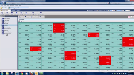
Trend, digital, and other real-time displays

Dedicated software (free download) is available for loading waveforms and GM settings
Universal viewer
Data files saved on the GM can be viewed and printed. You can perform statistical computation over an area and export to ASCII, Excel, or other formats.

Offline setting software
Save settings or transfer them to the GM. Connections can also be made easily via USB or Bluetooth.

Safe to use in a wide range of temperatures
With operating temperatures of -20 °C to 60 °C, it supports a wide range of applications without concern about the installation environment.

Monitoring and settings can also be done on a tablet
Supports Bluetooth (optional code /C8)
You can enter settings or monitor from a tablet without ever bringing a PC to the site. Dedicated applications is available for free download. For more information, visit our website.
Enables monitoring via Bluetooth
Bluetooth supports Android only.

Enables monitoring via Wi-Fi
Wi-Fi supports both Android and iOS.

Powerful applications
Bluetooth connection
Simple to use for in-vehicle testing.

USB connection
Service staff can easily perform maintenance on the GM.

Data analysis made simple and mobile
High speed measurement (down to 1 ms)
Yokogawa's proprietary A/D converter allows the high speed module to measure data points as fast 1ms.
- High speed (1 ms) measurement*
- Proprietary A/D converter
* With 1ch per module. At 2 ms, 2 ch per module, and at 5 ms or more, all 4 ch per module.

| Model | Scan interval | ||
|---|---|---|---|
| 1ms | 5ms | 10ms | |
| GM10-1 | 1ch | 5ch | 10ch |
| GM10-2 | 5ch | 25ch | 32ch |
Dual interval measurement with two different scan intervals
Users have the ability to choose two different scan intervals on a single GM system. This allows users the flexibility to measure various types of inputs with two different scan intervals in a single system. For example, this provides for efficient, simultaneous measurement of signals with slow fluctuations such as temperature, and fast-changing signals such as pressure and vibration. Modules can be assigned to measurement groups.

PID control function
Control function
Enables PID and program control
- PID control module
2-loops per module, up to 20 loops per system - Setpoint program control function (/PG option)
Up to 99 patterns

Remote operation and monitoring
The web application enables remote operation and monitoring from a browser.

MATH (including reports), and event actions
MATH function (/MT option)
Supports various kinds of math computation, including basic math and functions (square root, logarithms, trigonometry). Write formulas using variables for measured or computed data and save or display the results—this saves time and effort on post-processing. Create hourly, daily, monthly, and other reports with the Report function.

Event actions
Ability to assign actions tied to specific events during the operation of the data acquisition station.

Aerospace Heat Treatment Supports heat treatment application AMS2750/NADCAP
Calibration correction schedule control function (/AH option)
Schedule management for periodically executing calibration correction configuration and the like. You can set the input correction factor as a sensor correction factor and instrument correction factor. TUS software is available for easily creating TUS (temperature uniformity survey) reports.*
* For details on TUS software, consult with your Yokogawa dealer.

Input calibration is performed in the AI channel setting screen, and the calibration period settings are entered in the schedule management setting screen.
Record data in separate files per equipment set
Multi-batch Function (/BT option)
Record pre-defined channel groups to separate data files with independent start and stop control. You can create up to 12 batches.


Report creation and network functions (/MT option)

Provides a variety of convenient networking functions
Modbus/TCP and Modbus/RTU Communications
GM supports Modbus TCP/IP client and server modes for Ethernet communications and Modbus/RTU master and slave modes for optional serial communications.
Modbus/TCP (Ethernet connection)
Using the Modbus/TCP and Modbus/RTU functions, you can display and save data from the server and slave devices on the GM.*
* Requires the communication channel (/MC option).

(You can connect up to 16 Modbus/TCP servers, or up to 32 servers with the GM10-2.)
(You can connect up to 31 Modbus/RTU slaves.)
Modbus/RTU (RS-422/485 connection)
Using the Modbus/TCP and Modbus/RTU functions, you can acquire GM data from upstream devices.

EtherNet/IP Function (/E1 option)
GM supports EtherNet/IP server functions. You can access GM from PLCs or other devices and load measurement/MATH channels or write to communication input channels*(GM10-1: up to 300 ch, GM10-2: up to 500 ch).
* Requires the communication channel option (/MC option).

CC-Link family SLMP communication (/E4 option)
Protocol function that enables connection from a GM to Mitsubishi Electric PLCs without sequencer programs. The GM can run as the SLMP client to write to a GM measured data PLC, or PLC data to communication channels*.
* Requires the communication channel option (/MC).

Data acquisition on power measuring instruments (/E2 and /MC options)
Acquire precise digital data on the GM by digital communication connectivity to a power measuring instrument (WT series power analyzers) and record it along with the GM's measured data. Since it records a device's power consumption, temperature, and other phenomena at the same time, the GM is ideal for performance evaluation testing.
- Models that can be connected:
Yokogawa Test&Measurement Corp.,
WT1800/WT1800E (command type WT1800), WT500, WT300/WT300E (command mode WT300) - Max. no. of connections: 16

OPC-UA Server (/E3 option)
Data acquired by the GM can be accessed through Ethernet communication from a host system (OPCUA client). Writing from upstream systems to GM communication channels requires the communication channel function (/MC option).

Comes with communication functions that are compatible with the DARWIN data acquisition unit
The GM supports DARWIN communication commands. Use your current DARWIN communication programs as-is on the GM. It's easy to switch from an existing DARWIN unit.
* See your dealer or nearest Yokogawa representative for details.

CENTUM/STARDOM communication package
- CENTUM: LFS2432, DARWIN/DAQSTATION Communication package (for ALE111 [Ethernet])
- STARDOM: NT365AJ DARWIN connection package
FTP-based file transfer
The FTP client/server functions allow you to easily share and manage data from a centralized file server

E-mail messaging function
The GM can send a variety of informative e-mail messages that include alarm notification reports, periodic instantaneous data values, scheduled report data and other information.

Automatic network setup (DHCP) function
Using Dynamic Host Configuration Protocol (DHCP), the GM can automatically acquire the settings it needs (IP address) for network communications from a DHCP server. This makes i6t easier than ever to install the unit on a plant network.

Time synchronization with network time servers
GM uses SNTP protocol in client mode to acquire time information from a network time-server. This function allows any number of GM units within a facility to have precisely synchronized time; all units will record data with coordinated date and time stamp information. In addition, GM can function as a server, providing time data to other SNTP client units on the network.

Rock-solid hardware and highly secure
Be confident that recorded data is saved
Supports long-duration and multichannel recording. Measured data is always stored to internal memory, and data is transferred to external storage media at regular intervals. Redundancy can be achieved by sending data to a server with the FTP client function. Securely saves measured data even in the event of a sudden power loss.

| Number of recording channels | Total sample time |
|---|---|
| 30 | Approx. 71 days |
| 100 | Approx. 23 days |
| 300 | Approx. 7 days |
With an internal memory of 1.2 GB and recording interval of 1 sec.
Select file formats according to your application
For increased security, measured data can be saved in binary format. This format is very difficult to decipher or modify in traditional text editors or other programs. To enable easy and direct opening of the data in text editors or spreadsheet programs, choose text format. This allows you to work with your measurement data without dedicated software.

ASCII data display

Binary data display
Security enhancements
Safely sends and receives customer data.

SSL: An encryption protocol for data sent over TCP/IP networks.
21 CFR Part 11 support (/AS option)
With the advanced security function option, GM supports the USA FDA's Title 21 CFR Part 11 regulations (for the pharmaceutical manufacturing industry). It gives you access to a login function for requiring user names, IDs, and passwords, plus electronic signatures, audit trails, an anti-tampering function, an Active Directory-based password management function, and other security features.
")
Key lock
You can use settings to lock the GM10 operation keys in order to avoid accidental start/stop of measurement or computation.

Analog front end module
A proprietary A/D converter delivers high speed, high precision data acquisition. (High-speed AI, PID Control module)

Standards supported

Analog input module

Specifications
| Model | GX90XA | ||||||||||||||||||||||||||||||||||||||||||||||||||||||||||||||||||||||||||||||||||||||||||||||||||||||||
|---|---|---|---|---|---|---|---|---|---|---|---|---|---|---|---|---|---|---|---|---|---|---|---|---|---|---|---|---|---|---|---|---|---|---|---|---|---|---|---|---|---|---|---|---|---|---|---|---|---|---|---|---|---|---|---|---|---|---|---|---|---|---|---|---|---|---|---|---|---|---|---|---|---|---|---|---|---|---|---|---|---|---|---|---|---|---|---|---|---|---|---|---|---|---|---|---|---|---|---|---|---|---|---|---|---|
| Input type (Inputs: 10) |
DC voltage*1, standardized signal*1, thermocouple*1, RTD*2, DI*1, DC current (with external shunt resistor)*1, DC current*3, resistance*4 | ||||||||||||||||||||||||||||||||||||||||||||||||||||||||||||||||||||||||||||||||||||||||||||||||||||||||
| DCV | 20 mV, 60 mV, 200 mV, 1 V, 2 V, 6 V, 20 V, 50 V, 100 V*5 | ||||||||||||||||||||||||||||||||||||||||||||||||||||||||||||||||||||||||||||||||||||||||||||||||||||||||
| Standard signal | 0.4-2 V, 1-5 V | ||||||||||||||||||||||||||||||||||||||||||||||||||||||||||||||||||||||||||||||||||||||||||||||||||||||||
| Resistance | 20, 200, 2000 Ω | ||||||||||||||||||||||||||||||||||||||||||||||||||||||||||||||||||||||||||||||||||||||||||||||||||||||||
| Thermocouple | R, S, B, K, E, J, T, N, W, L, U, W97Re3-W75Re25, KpvsAu7Fe, Platinel 2, PR20-40, NiNiMo, W/WRe26, N(AWG14), XK GOST | ||||||||||||||||||||||||||||||||||||||||||||||||||||||||||||||||||||||||||||||||||||||||||||||||||||||||
| RTD | Pt100, JPt100, Cu10 GE, Cu10 L&N, Cu10 WEED, Cu10 BAILEY, Cu10 (20°C) α=0.00392, Cu10 (20°C) α=0.00393, Cu25 (0°C) α=0.00425, Cu53 (0°C) α=0.00426035, Cu100 (0°C) α=0.00425, J263B, Ni100 (SAMA), Ni100 (DIN), Ni120, Pt25, Pt50, Pt200 WEED, Cu10 GOST, Cu50 GOST, Cu100 GOST, Pt46 GOST, Pt100 GOST, PT500*4, PT1000*4 | ||||||||||||||||||||||||||||||||||||||||||||||||||||||||||||||||||||||||||||||||||||||||||||||||||||||||
| DI | Level, Contact | ||||||||||||||||||||||||||||||||||||||||||||||||||||||||||||||||||||||||||||||||||||||||||||||||||||||||
| DC current | 0-20 mA, 4-20 mA | ||||||||||||||||||||||||||||||||||||||||||||||||||||||||||||||||||||||||||||||||||||||||||||||||||||||||
| Scan intervals |
1/2/5/10/20/50/100/200/500ms, 1/2/5s Scan interval by type
|
||||||||||||||||||||||||||||||||||||||||||||||||||||||||||||||||||||||||||||||||||||||||||||||||||||||||
| Power supply and consumption | Supplied from main unit, power consumption: 2 W or less | ||||||||||||||||||||||||||||||||||||||||||||||||||||||||||||||||||||||||||||||||||||||||||||||||||||||||
| Insulation resistance | Between input circuits and internal circuitry: 20 MΩ or greater (at 500 V DC) | ||||||||||||||||||||||||||||||||||||||||||||||||||||||||||||||||||||||||||||||||||||||||||||||||||||||||
| Withstand voltage | Between the input circuits and the internal circuitry: 3000 VAC for one minute (current input type and low withstand voltage type: 1500 VAC for one minute) Between analog input channels: 1000 V AC for one minute (excluding b terminals for universal input type) (low withstand voltage type: 400 VAC for one minute, high speed universal type: 3000 V AC for one minute) |
||||||||||||||||||||||||||||||||||||||||||||||||||||||||||||||||||||||||||||||||||||||||||||||||||||||||
| Terminal types | M3 screw terminals or clamp terminals | ||||||||||||||||||||||||||||||||||||||||||||||||||||||||||||||||||||||||||||||||||||||||||||||||||||||||
| Weight | Approx. 0.3 kg | ||||||||||||||||||||||||||||||||||||||||||||||||||||||||||||||||||||||||||||||||||||||||||||||||||||||||
*1 Cannot be set for the current input type (type suffix code: -C1) or 4-wire RTD/resistance type (type suffix code: -R1).
*2 Cannot be set for the current input type (type suffix code: -C1), electromagnetic relay type (type suffix code: -T1), or low withstand voltage type (type suffix code: -L1).
*3 Can only be set with current input type (type suffix code: -C1).
*4 Can only be set with 4-wire RTD/resistance type (type suffix code: -R1).
*5 Can only be set with high speed universal type (type suffix code: -H0).
Model and Suffix Codes
| Model | Suffix Code | Description | ||||
|---|---|---|---|---|---|---|
| GX90XA | Analog input module | |||||
| Number of channels | -04 | 4 channels (-H0 type only) | ||||
| -06 | 6 channels (-R1 type only) | |||||
| -10 | 10 channels | |||||
| Type | -C1 | Current, scanner type (isolated between channels) | ||||
| -L1 | Low withstand voltage DCV/TC/DI, scanner type (isolated between channels) | |||||
| -U2 | Universal, Solid state relay scanner type (3-wire RTD b-terminal common) | |||||
| -T1 | DCV/TC/DI, Electromagnetic relay scanner type (isolated between channels) | |||||
| -H0 | High speed universal, individual A/D type (isolated between channels) | |||||
| -R1 | 4-wire RTD/resistance, scanner type (isolated between channels) | |||||
| - | N | Always N | ||||
| Terminal form | -3 | Screw terminal (M3) | ||||
| -C | Clamp terminal | |||||
| Area | N | General | ||||
Analog output module

Specifications
| Model | GX90YA |
|---|---|
| Output type (outputs: 4) | Transmission output, manual output |
| Range | 4–20 mA or 0–20 mA |
| Output update interval | 100 msec (shortest) |
| Load resistance | 600 Ω or less |
| Resolution | 0.002% |
| Power supply and consumption | Supplied from main unit, power consumption: 3W or less |
| Insulation resistance | Between output circuits and internal circuitry: 20 MΩ (at 500 VDC) |
| Between output channel terminals: 500 VDC, 20 MΩ or greater | |
| Withstand voltage | Between output circuits and internal circuitry: 1500 AC for one minute |
| Between output circuits: 500 VAC for one minute | |
| Terminal type | M3 screw terminals or clamp terminals |
| Weight | Approximately 0.2 kg |
Model and Suffix Codes
| Model | Suffix Code | Description | ||||
|---|---|---|---|---|---|---|
| GX90YA | Analog output module | |||||
| Number of channels | -04 | 4 channels | ||||
| Type | -C1 | Current output (isolated between channels) | ||||
| - | N | Always N | ||||
| Terminal form | -3 | Screw terminal (M3) | ||||
| -C | Clamped terminals | |||||
| Area | N | General | ||||
Digital input module

Specifications
| Model | GX90XD | |
|---|---|---|
| Input types (Inputs: 16) |
DI or pulse input*1 (Open collector or non-voltage contact) | |
| ON/OFF detection | Open collector: Voltage of 0.5 V DC or less when ON, leakage current of 0.5 mA or less when OFF Non-voltage contact: Resistance of 200 Ω or less when ON, 50 kΩ when OFF |
|
| Contact rating | 12 V DC, 20 mA or more | |
| Power supply and consumption | Supplied from main unit, power consumption: 0.7 W or less | |
| Insulation resistance | Between input terminals and internal circuitry: 20 MΩ or greater (at 500 V DC) | |
| Withstand voltage | Between input terminals and internal circuitry: 1500 V AC for one minute | |
| Terminal types | M3 screw terminals or clamp terminals | |
| Weight | Approx. 0.3 kg | |
Pulse input specifications*1
| Counting system | The rising edge of the pulse is counted. |
|---|---|
| Max. pulse period | 250Hz (The chattering filter : OFF) 125Hz (The chattering filter : ON) |
| Minimum detection pulse width | Low (close), High (open), both is 2 ms or more |
| Pulse detection period | 1ms |
| Pulse measurement accuracy | ± 1 pulse |
| Pulse count interval | Measurement interval |
|
Filter |
The chattering filter can be switched On/Off. (When the chattering filter is off, connect GX/GP so that it is not affected by the noise.) |
*1 Integration requires the math function (optional code /MT).
Model and Suffix Codes
| Model | Suffix Code | Description | ||||
|---|---|---|---|---|---|---|
| GX90XD | Digital input module | |||||
| Number of channels | -16 | 16 channels | ||||
| Type | -11 | Open collector/Non-voltage, contact (shared common), Rated 5 VDC | ||||
| - | N | Always N | ||||
| Terminal form | -3 | Screw terminal (M3) | ||||
| -C | Clamp terminal | |||||
| Area | N | General | ||||
Digital output module

Specifications
| Model | GX90YD |
|---|---|
| Output types (outputs: 6) | Relay contact (c contact) |
| Rated load voltage | 100 to 240 V AC or 5 to 24 V DC |
| Max. load voltage/current | 264 VAC or 26.4 VDC, 3A/point (resistance load) |
| Power supply and consumption | Supplied from main unit, power consumption: 1.4 W or less |
| Insulation resistance | Between output terminals and internal circuitry: 20 MΩ (at 500 VDC) |
| Withstand voltage | Between output terminals and internal circuitry: 3000 V AC for one minute |
| Terminal types | M3 screw terminals |
| Weight | Approx. 0.3 kg |
Model and Suffix Codes
| Model | Suffix Code | Description | ||||
|---|---|---|---|---|---|---|
| GX90YD | Digital output module | |||||
| Number of channels | -06 | 6 channels | ||||
| Type | -11 | Relay, SPDT(NO-C-NC) | ||||
| - | N | Always N | ||||
| Terminal form | -3 | Screw terminal (M3) | ||||
| Area | N | General | ||||
Expansion module

Model and Suffix Codes
| Model | Suffix Code | Description | ||||
|---|---|---|---|---|---|---|
| GX90EX | I/O expansion module | |||||
| Port | -02 | 2 Ports | ||||
| Type | -TP1 | Twisted pair cable | ||||
| - | N | Always N | ||||
| Area | -N | Standard accessories | ||||
Digital input/output module

Specifications
| Model | GX90WD | |
|---|---|---|
| Input types (Inputs: 8) |
DI or pulse input*1 (Open collector or non-voltage contact) | |
| ON/OFF detection | Open collector : Voltage of 0.5 V DC or less when ON, leakage current of 0.5 mA or less when OFF Non-voltage contact : Resistance of 200 Ω or less when ON, 50 kΩ when OFF |
|
| Contact input rating | 12 VDC, 20 mA or more | |
| Output type (outputs: 6) | Relay contact (C contact) | |
| Rated load voltage | When connected to the main circuit (fi rst-order power supply), 150 VAC or less When connected to a circuit derived from the main circuit (second-order power supply), 250 VAC or less (the main circuit is 300 VAC or less and uses an isolated transformer) or 30 VDC or less |
|
| Max. load current | 2 A (DC)/2 A (AC), resistive load | |
| Power consumption | 1.9 W or less | |
| Insulation resistance | Between input terminals and internal circuitry: 20 MΩ or greater (at 500 VDC) Between output terminals and internal circuitry: 20 MΩ or greater (at 500 VDC) |
|
| Withstand voltage | Between input terminals and internal circuitry: 1500 VAC for one minute Between output terminals and internal circuitry: 3000 VAC for one minute |
|
| Terminal types | M3 screw terminals | |
| Weight | Approx. 0.3 kg | |
Each unit (GX/GP main unit and expandable I/O), can use 1 module only.
Pulse input specifications*1
| Counting system | The rising edge of the pulse is counted. |
|---|---|
| Max. pulse period | 250Hz (The chattering filter : OFF) 125Hz (The chattering filter : ON) |
| Minimum detection pulse width | Low (close), High (open), both is 2 ms or more |
| Pulse detection period | 1ms |
| Pulse measurement accuracy | ± 1 pulse |
| Pulse count interval | Measurement interval |
|
Filter |
The chattering filter can be switched On/Off. (When the chattering filter is off, connect GX/GP so that it is not affected by the noise.) |
*1 Integration requires the math function (optional code /MT).
Model and Suffix Codes
| Model | Suffix Code | Description | ||||
|---|---|---|---|---|---|---|
| GX90WD | Digital input/output module | |||||
| Number of channels | -0806 | 8 channel DIs, 6 channel DOs | ||||
| Type | -01 | Open collector/non-voltage contact (shared common), rated 5 VDC; Relay, SPDT, (NO-C-NC) | ||||
| - | N | Always N | ||||
| Terminal form | -3 | Screw terminal (M3) | ||||
| Area | N | General | ||||
Pulse input module

Specifications
| Model | GX90XP |
|---|---|
| Number of inputs | 10 |
| Measurement interval | 100 ms (shortest) |
| Input type | Contact (open collector, voltage-free contact), level (5 V logic) |
| Input range | Up to 20 kHz* * 30 Hz when the chattering filter is in use (On) |
| Minimum detection pulse width | 25 μs* * 15 ms when the chattering filter is in use (On) |
| Measurement accuracy | Count ± 1 pulse During integration, the following accuracies are added. Upon MATH start: +1 measuring period Upon MATH stop: -1 measuring period * Integration requires the math function (optional code /MT). |
| Chattering filter | Removes chattering up to 5 ms (can be turned on/off on each channel) |
| Hysteresis width | Approx. 0.2 V |
| Contact, transistor rating | Contact: 15 V DC or higher and 30 mA or higher rating. Minimum applicable load current 1 mA or less. Transistor: With the following ratings: Vce > 15 VDC, Ic > 30 mA |
| Maximum input voltage | ±10 V DC |
| Insulation resistance | Between input terminals and internal circuitry: 20 MΩ or greater at 500 V DC |
| Withstand voltage | Between input terminals and internal circuitry: 1500 V AC for 1 minute |
Model and Suffix Codes
| Model | Suffix code | Description | ||||
|---|---|---|---|---|---|---|
| GX90XP | Pulse input module | |||||
| Number of channels | -10 | 10 channels | ||||
| Type | -11 | DC voltage/open collector/non-voltage contact (shared common), rated 5 VDC | ||||
| — | N | Always N | ||||
| Terminal form | -3 | Screw terminal (M3) | ||||
| -C | Clamp terminal | |||||
| Area | N | General | ||||
PID control module

Specifications
| Model | GX90UT | |
|---|---|---|
| Control loops | Number of loops | 2 |
| Analog input (measured input) | Measured points | 2 |
| Measurement type | DC voltage (DCV)/standardized signal, TC/RTD, DI (LEVEL and non-voltage contact)/DC current (with external shunt resistance) | |
| Scan (control) interval | 100 ms or 200 ms (system global setting) | |
| Analog output (control output/transmission output/sensor power supply) | Outputs | 2 |
| Output type | Power supply for current, voltage pulse, or sensors. | |
| Current output: 4-20 mA or 0-20 mA | ||
| Voltage pulse output: ON voltage = 12 VDC or more (load resistance 600 Ω or more), OFF voltage = 0.1 VDC or less | ||
| Can be used as a sensor power supply (13.0-18.3 VDC) | ||
| Digital input (switching the SP, operation mode, etc.) | Inputs | 8 |
| Input format | Non-voltage contact and open collector | |
| Contact rating: 12 VDC or more, 20 mA or more | ||
| Digital output (of alarms, events, etc.) | Outputs | 8 |
| Output format | Open collector (sink type) | |
| Output contact capacity | Max 24 VDC, 50 mA | |
| Withstand voltage/insulation resistance | See PID control module general specifications (GS 04L51B01-31EN) | |
| Terminal type | M3 screw terminals | |
| Weight | Approximately 0.3kg | |
Model and Suffix Codes
| Model | Suffix Code | Description | ||||
|---|---|---|---|---|---|---|
| GX90UT | PID control module | |||||
| Number of loops | -02 | 2 loops | ||||
| Type | -11 | 8 DIs, 8 DOs | ||||
| — | N | Always N | ||||
| Terminal form | -3 | Screw terminals (M3) | ||||
| Area | N | General | ||||
as of March, 2017
The SD cards of the following manufacturers have been verified for use with SMARTDAC+® GX/GP/GM, µR10000™/µR20000™ and FX1000™. However, please note that Yokogawa does not guarantee normal operation of the SD card when using with products listed below.
SMARTDAC+ GX
Applicable Models: GX10, GX20, GX20W
SMARTDAC+ GP
Applicable Models: GP10, GP20
SMARTDAC+ GM
Applicable Models: GM10
| Manufacturer | Capacity | Manufacturer Model | GX10 | GX20 | GP10 | GP20 | GX20W | GM10 |
|---|---|---|---|---|---|---|---|---|
| SanDisk | 16GB | SDSDXS-016G | √ | √ | √ | √ | √ | |
| SanDisk | 8GB | SDSDXS-008G | √ | √ | √ | √ | √ | |
| SanDisk | 32GB | SDSDXVE-032G | √ | √ | √ | √ | √ | √ |
| SanDisk | 32GB | SDSDXS-032G | √ | √ | √ | √ | √ | √ |
| SanDisk | 32GB | SDSDXL-032G | √ | √ | √ | √ | √ | √ |
| SanDisk | 16GB | SDSDXL-016G | √ | √ | √ | √ | √ | √ |
| SanDisk | 8GB | SDSDXL-008G | √ | √ | √ | √ | √ | √ |
Applicable Models: µR10000/EM1, µR20000/EM1
| Manufacturer | Capacity | Manufacturer Model | µR10000/EM1 | µR20000/EM1 |
|---|---|---|---|---|
| SanDisk | 32GB | SDSDXVE-032G | √ | √ |
| SanDisk | 32GB | SDSDXS-032G | √ | √ |
Applicable Models: FX1000
| Manufacturer | Capacity | Manufacturer Model | FX1000 | |
|---|---|---|---|---|
| SanDisk | 32GB | SDSDXVE-032G | √ | |
| SanDisk | 32GB | SDSDXS-032G | √ | |
In rare cases, the SD card is not recognized or generates an error when inserted into the instrument. If this occurrs, try the following.
- Eject the SD card, then reinsert it.
- Replace with a SD card that you know to be working normally.
- Format the SD card on the Products (all data on the card will be deleted).
Please direct inquiries regarding the other manufacturers' verified SD cards above to their manufacturers.
Please note that sales of the above-mentioned SD card may be discontinued from the manufacturer without prior notice.
-
List of Verified SD Memory Cards (SD Cards)
The SD cards of the following manufacturers have been verified for use with SMARTDAC+ GX/GP/GM, μR10000/μR20000 and FX1000. However, please note that Yokogawa does not guarantee normal operation of the SD card when using with products listed below.
-
List of RoHS
This is a list of recorder and controller products that support the RoHS (2011/65/EU) directive.
-
New Legislative Framework (NLF) Conforming Products
This is a list of recorder and controller products that support the New Legislative Framework (NLF.)
Resources
Improving manufacturing efficiency demands constant action - from uncovering operational waste to identifying areas for continuous improvement. Namely, we must always pursue a cycle of visualizing, analyzing, and solving energy saving challenges.
Transform your clean room from a cost center into a sustainable asset. Optimize yields and minimize carbon footprints with Yokogawa’s autonomous sensing technology.
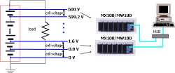
The SMARTDAC+ GM is best suited for applications where the voltage of each cell in fuel cells, secondary batteries and electrolyzers is measured.

Supporting next-generation hydrogen production processes toward carbon neutrality by optimizing electrolyzer operations. This application utilizes Cell Voltage Measurement (CVM) to maximize hydrogen output and reduce power consumption.

Customers want to improve maintenance by predicting failures of existing durable equipment. However, existing equipment do not have enough space, and it is not easy to increase the number of sensors needed to grasp the condition.
To address this issue, the VZ20X’s compact size allows it to be installed between equipment, and data collection can be easily monitored via Ethernet (Modbus/TCP).


the VZ20X installed near sensors such as temperature, humidity, and vibration, and enables automatic collection of data via the factory LAN. The data collection, monitoring and management can be automatically and regularly monitored with the data logging software GA10. As a result, it contributes to reducing the workload of workers.

AN 04L51B01-02EN

AN 04L51B01-03EN

Customers want to improve maintenance by predicting failures of existing durable equipment. However, existing equipments do not have enough space, and it is not easy to increase the number of sensors needed to grasp the condition.
To address this issue, the VZ20X’s compact size allows it to be installed between equipments, and data collection can be easily monitored via Ethernet (Modbus/TCP).

AN 04L51B01-01EN

The SMARTDAC+ GM is used extensively for data acquisition in various kinds of conveyance equipment including automobiles, industrial vehicles, in-plant vehicles, ocean shipping vessels, and automated materials handling systems. In addition to being compact and not requiring a PC for data acquisition, the SMARTDAC+ GM can be run under DC power and be operated under harsh conditions (-20° to 60°).

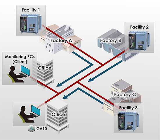
The SMARTDAC+ GM10 is employed by customers who are device manufacturers when they deliver a device to the end user, for on-site monitoring to check that the delivered device is operating stably. If settings are made to the SMARTDAC+ GM10 in the office beforehand, then all that is necessary is to take it to the site and begin data acquisition thus, anyone can conduct on-site data acquisition.

- For remote monitoring (of temperature, pressure, and flow volume), installing the SMARTDAC+ GM in the plant and the SMARTDAC+ GX in the office provides for a scalable, pc-free on-site data monitoring solution.
- You can centralize management of large quantities of data by automatically transferring acquired data to a FTP server.

In durability testing of engines, revolutions and load control signals are applied and the results are acquired on a recorder. Using the Data Acquisition System SMARTDAC+ GM's PID control module, you can record data while simultaneously applying control signals.

Data acquired on the SMARTDAC+ GM can be easily monitored through the company network, even from remote locations.
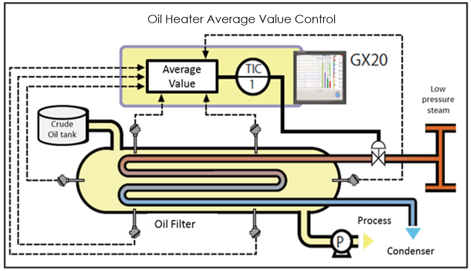
The GX20 and GX90UT offer an average value computation function making it ideal for controlling temperature and other fluctuating phenomena. The operating status can be controlled in real time, providing operating cost reductions.
Downloads
Brochures
- SMARTDAC+ Data Acquisition & Control Data Acquisition System GM (8.2 MB)
- SMARTDAC+ Advanced Security Function Data Integrity Support for pharmaceutical & medical standards (1.3 MB)
- SMARTDAC+ series Easy connection to PROFINET devices (787 KB)
- SMART 920 (4.0 MB)
- SMART 920, 920 MHz band wireless communication instrument series (For US market only) (5.6 MB)
- SMARTDAC+, the best-selling paperless recorder (data logger), now supports PROFINET! (1.3 MB)
- Power monitoring package SMARTDAC+ GM / UPM100 (2.4 MB)
Instruction Manuals
- Precaution on the use of SMARTDAC+ (664 KB)
- Data Acquisition System GM First Step Guide (9.4 MB)
- Data Acquisition System GM User's Manual (14.5 MB)
- SMARTDAC+ STANDARD IP Address Configurator (782 KB)
- Model GX10/GX20/GP10/GP20/GM10 Communication Command User's Manual (3.6 MB)
- Handling of the SD Memory Card (321 KB)
- SMARTDAC+ STANDARD Hardware Configurator User's Manual (4.4 MB)
- Model GX10/GX20/GP10/GP20/GM10/GX90NW PROFINET Communication User's Manual (4.5 MB)
- SMARTDAC+ STANDARD Universal Viewer User's Manual (4.2 MB)
- Regarding the Downloading and Installing for the Software, Manuals and Labels/About the Usage of Open Source Software (367 KB)
- Data Acquisition System GM Advanced Security Function (/AS) User's Manual (4.3 MB)
- Cloud Equipment/Quality Predictive Detection Tool User’s Manual (166 KB)
- Model 773230 Downloading the Validation Documents (132 KB)
- Model GX10/GX20/GP10/GP20/GM10 Multi-batch Function (/BT) User’s Manual (3.5 MB)
- Model GX10/GX20/GP10/GP20/GM10 EtherNet/IP Communication (/E1) User’s Manual (1.8 MB)
- Model GX10/GX20/GP10/GP20/GM10 WT Communication (/E2) User’s Manual (1.5 MB)
- Model GX10/GX20/GP10/GP20/GM10 OPC-UA Server (/E3) User’s Manual (884 KB)
- GX20/GP20 (/CM2 and /CM3 options), GM10 (/CM2, /CS2, /CM3 and /CS3 options) 920MHz wireless communication First Step Guide_US,KR (1.3 MB)
- Model GX10/GX20/GP10/GP20/GM10 SLMP Communication (/E4) User's Manual (2.1 MB)
- Model GX10/GX20/GP10/GP20/GM10 Log Scale (/LG) User’s Manual (1011 KB)
- Model GX10/GX20/GP10/GP20/GM10 Loop Control Function, Program Control Function (/PG Option) User’s Manual (24.3 MB)
- Notes on using the Model GX90EX expansion module (I/O expansion module) (194 KB)
- Model GX20/GP20/GM10, UT52A/UT32A, UPM100 920 MHz Wireless Communication, MH920 Console International (For the US and the Korea) (12.0 MB)
General Specifications
- Data Acquisition System GM (3.7 MB)
- GX60 I/O Base Unit (Expandable I/O), GX90EX Expansion Module (3.1 MB)
- GX90XA/GX90XD/GX90YD/GX90WD/GX90XP/GX90YA I/O Modules (4.6 MB)
- GX90UT PID Control Module, GX10/GX20/GP10/GP20, GM, Loop Control Function, Program Control function (/PG) (1.8 MB)
- Equipment/Quality Predictive Detection Tool (340 KB)
- Model 773230 Validation Document for SMARTDAC+ (for the /AS option) (355 KB)
- 415940, 415941 and 415942 Shunt Resistor for Screw Input Terminal (178 KB)
- List of the US Toxic Substances Control Act (TSCA) Compliant Recorder and Controller Products (176 KB)
- 438920, 438921 and 438922 Shunt Resistor for Clamp Input Terminal (252 KB)
- List of RoHS (2011/65/EU) Directive Compliant Products (6-substances RoHS compliant products) (356 KB)
- GX20/GP20 (/CM2 option) GM (/CM2 and /CS2 options) 920MHz Wireless Communication (2.3 MB)
- New Legislative Framework (NLF) Conforming Products (362 KB)
Software
- Hardware Configurator *Log-in Required
- Universal Viewer *Log-in Required
- IP Address Configurator for GM10 *Log-in Required
- GA10 Data Logging Software *Log-in Required
- GA10 Data Logging Software [60-day free trial] *Log-in Required
- Offline version: Equipment/Quality Predictive Detection tool OE10 *Log-in Required
- Validation Document for SMARTDAC+ *Log-in Required
- EtherNet/IP Profile (EDS file) for GM10 *Log-in Required
- PLC Communication Protocol Profile (EDS file) for GM10 (For connecting OMRON's PLCs) *Log-in Required
- SMARTDAC+ Report Template Builder *Log-in Required
- SMARTDAC+ Excel Report Simulator *Log-in Required
- SMARTDAC+ SettingFileConverter Settings File Conversion Tool *Log-in Required
- Mobile WEB Application for GX/GP/GM *Log-in Required
- GM Mobile Tool *Log-in Required
- SD Card Formatter *Log-in Required
- USB Driver for GM10 *Log-in Required
- LabVIEW Driver (for SMARTDAC+ Series) *Log-in Required
- GM10 Firmware *Log-in Required
- SMARTDAC+ I/O Module Firmware *Log-in Required
- SMARTDAC+ I/O Expansion Module Firmware *Log-in Required
- SMARTDAC+ PID Control Module Firmware *Log-in Required
- MH920 Wireless Communication module (Coordinator) Firmware *Log-in Required
- MH920 Wireless Communication module (Router) Firmware *Log-in Required
Technical Information
- Data Acquisition System Introduction to the Various Features of the GM (2.8 MB)
- Effectively Using SMARTDAC+; Software Introduction (6.1 MB)
- SMARTDAC+ GM Advanced Security Functions White Paper for FDA 21 CFR Part 11 (503 KB)
- Reduce Risk by Eliminating Paper Chart Records (1.3 MB)
- DARWIN Replacement Guide (9.1 MB)
- High-speed Measurement Application High-speed Measurement/ Dual Interval Measurement Feature LR Replacement (8.9 MB)
- Recorders, Data Loggers, and Control Products Security Standard (488 KB)
- SMARTDAC+ Loop Control Function, Program Control Function (/PG Option) (9.5 MB)
Certificates
- EU DECLARATION OF CONFORMITY for GM10 (189.6 KB)
Engineering Tools
- Analog Input Module GX90XA (531 KB)
- Expandable I/O GX60 (575 KB)
- SMARTDAC+ GM Data Acquisition System (1.8 MB)
- Analog Output Module GX90YA (265 KB)
- Pulse Input Module GX90XP (329 KB)
- Digital Input/Output Module GX90WD (229 KB)
- Digital Output Module GX90YD (267 KB)
- Digital Input Module GX90XD (378 KB)
- Expansion Module GX90EX (207 KB)
Videos
Smart user interface, smart architecture, and smart functionality is achieved in the Yokogawa SMARTDAC+ data acquisition and control product series.
SMARTDAC+ consists of the GX and GP touch screen data acquisition stations and the most recent addition – the GM data acquisition and data logging system which is both compact and modular.

This video explains the value brought by AI, and introduces Yokogawa's AI initiatives and three solutions. Autonomous Control AI (FKDPP) received the Prime Minister's Award at the 52nd Japan Industrial Technology Awards.
News
-
Press Release | Solutions & Products Jul 5, 2018 Yokogawa adds high-voltage analog input module to OpreX™ Data Acquisition lineup
Yokogawa adds high-voltage analog input module to OpreX™ Data Acquisition lineup.
Looking for more information on our people, technology and solutions?
Contact Us