- With an Ohm meter check the following wires on the ISC40G sensor cable:
- 11 to 12 (Pt1000 or Thermistor)
- 13 to 17 – Sensor coil – expect low resistance. If unstable or above 100Ω it is bad.
- 15 to 16 - Sensor coil – expect low resistance. If unstable or above 100Ω it is bad.
- 14 to every other wire – The ohm meter should stay off scale. If the ohm meter moves/jumps/reads anything that is bad.
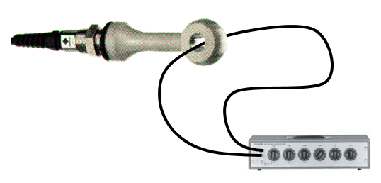
Simulating a conductivity reading on an ISC convertor.
- You will need:
- A known working ISC Converter
- A piece of wire
- One or two decade box/resistance sources.
- Connect sensor wires 13-17 to analyzer.
- Connect wire through the toroidal sensor and connect the wire to the decade box. Be sure not to cross the leads or wire.
- Use second decade box resistance source to simulate the temp sensor.
- If you don’t have a second resistance source you can just connected the temp sensor wires 11&12 from the sensor, you will just not be able to vary the input readings.
- Write down the Cell Constant, change it to 1.000
- Set the temperature to the reference temperature or: Write down the Temp. Compensation method, and change it to “None.”
- The Conductivity reading should be 1/R where R = Resistance on the decade box.
- If you need higher resistance than the decade box you can use multiple loops of wire through the sensor. The reading will be L2 / R where L = Number of loops, R = Resistance on the decade box.
- Return all settings to the original settings when finished.
Productos y Soluciones Relacionadas
-
Conductivity Analyzers
Maintain and control even the most demanding process applications
-
Conductivity Sensors
Measure aqueous solutions quickly and reliably
-
High Conductivity Sensors ISC40/SC42
Precision sensors and instruments for extreme conditions
-
Liquid Analyzers
Increase process optimization and control
-
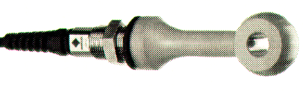
Toroidal/Inductive Conductivity Sensor ISC40
Superior conductivity measurement reliability, accuracy, and rangeability