


AI(인공지능)와 확장성을 갖춘 페이퍼리스 레코더
산업 공정, 테스트 실험실과 같은 환경에서는 제품 개발, 제품 테스트 및 제조 설계, 검증, 서비스 단계에서 엄격하고 지속적인 모니터링을 필요로 합니다. GP 시리즈는 휴대용과 벤치탑 사용을 가능하게 하는 손잡이와 발판이 있는 Yokogawa의 최신 레코더입니다.
GP 시리즈는 업계 최초의 멀티포인트 터치 패널을 탑재, 직관적이고 스마트한 사용자 제어 기능을 갖추었습니다. 사용자는 방진 및 방수 디스플레이에 과거 데이터를 스크롤, 팬으로 이동, 확대/축소할 수 있으며, 메시지까지 작성할 수 있습니다. 업계 최고의 신뢰성과 측정 정확도를 제공합니다. GP 시리즈는 장기간의 물리적 또는 전기적 트랜드를 모니터링하거나 문제를 확인하는 것에 최적화되어 있습니다.
보다 쉽게, 보다 편리하게
업계 최초! AI(인공지능) 탑재 설비/품질의 쉬운 예방 검출
- 설비/품질 예방 검출:
과거 기록된 데이터에서 예측 탐지 모형을 쉽게 생성하여 제조 장비 및 제품의 이상 예측을 조기에 탐지할 수 있습니다.

- 미래 펜(Pen):
복잡한 설정 없이 모니터링할 채널을 미래 펜으로 등록하고 가까운 미래를 파형으로 그리기만 하면 됩니다.
> Click here for details on AI Predictive Detection and Future pen
> AI 관련 제품들: AI Product Solutions page
열처리 응용을 위한 항공우주 산업의 AMS2750/NADCAP 및 자동차 산업의 CQI-9 지원(옵션)
캘리브레이션 등을 주기적으로 실행하기 위한 일정관리 자동차 업계 주요 기업에서 채택한 열처리 기준 CQI-9 준수.
> Heat treatment special site
FDA 21 CFR Part 11 지원, EU-GMP Annex 11, 데이터 무결성

고급 보안 기능을 통해 안전하게 사용할 수 있습니다. 고급 보안 기능 옵션(/AS)의 확장으로 미국 FDA 21 CFR Part 11, EU-GMP Annex 11, ALCOA +에 따른 데이터 무결성을 준수할 수 있습니다.
> What is "ALCOA +"?
Download technical data:
아날로그 측정과 관련하여, 자주 묻는 질문이 정리되어져 있습니다. [Basic], [Applied], [Noise Countermeasures] > Download
About OpreX
OpreX는 Yokogawa의 산업 자동화(IA) 및 제어 비즈니스를 포괄하는 브랜드로관련 기술과 솔루션의 우수성을 의미합니다. 카테고리와 각 카테고리 아래의 패밀리로 구성됩니다. 이 제품은 OpreX Measurement 카테고리에 속하는 OpreX Data Acquisition에 속합니다.
Details
AI를 활용한 예방 모니터링
설비/품질 에 관한 쉬운 예방 검출
* 예측 탐지 모델 및 프로파일 파형을 생성하려면 설비/품질 예측 검출 Tool(별도 판매)이 필요합니다.
Health Monitor 기능을 통해 프로세스 및 장비의 품질을 쉽게 확인 가능
과거 기록된 OK/NG(Not Good) 데이터에서 예측 검출 모델을 쉽게 만들어 GX/GP에 로드하면 제조 설비의 이상 예측 및 제품 품질 저하를 조기에 검출할 수 있으며, 정상 및 비정상 데이터의 정도를 보여주는 건강 점수는 여러 데이터 간의 상관 관계를 고려하여 판단하기 때문에 사람이 감지하기 어려운 이상 예측을 포착할 수 있습니다.
- 최대 채널 수 : 20
- 최속 레코더 인터벌 : 100 ms
- 타겟 채널 : I/O 채널, 연산 채널, 통신 채널
- 예방 검출 모델로 사용 가능한 파일:
[Yokogawa 제품] SMARTDAC+, DXAdvanced
[타사 제품] KEYENCE : TR-W1000, TR-W500 csv file, CHINO : KR2000, KR3000 csv file, EUROTHERM : 6100A, 6180A csv file

Health monitor 기능이 주는 장점:
- 설비 오작동 및 제품 품질 저하 전에 유지 및 보수 수행
- 설비 열화 및 품질 저하 정도 정량화
- 현장에서 설비/품질 예측 탐지 시스템을 쉽게 구축

프로파일 기능은 비정상적인 현상에 대한 실시간 경고를 제공합니다.
이 파형은 과거 기록된 데이터에서 프로파일 파형을 생성하여 GX/GP에 로드함으로써 공정 값의 임계값으로 사용할 수 있습니다. 프로파일 파형은 시간이 지남에 따라 공정 값이 변경되는 응용 분야에서도 유용합니다. 또한 기준 파형과의 편차를 화면에서 확인할 수 있습니다.
- 최대 채널 수: 20
- 최속 레코딩 인터벌: 500 ms */MC 옵션 필수

프로파일 기능이 주는 장점:
- 초기 상승을 포함한 전체 프로세스에 대한 알람 모니터링 및 설정
- 현재 프로세스 값과 이상적인 파형 비교

검증된 효과 및 예측 탐지의 활용 사례는 application notes를 참조하십시오.


60일 무료 채험판!* 설비/품질 예방 검출
예측 탐지 모델 및 프로파일 파형을 생성하여 Cloud 또는 Offline Equipment/Quality Predictive Detection Tool(별도 지급)이 필요하며, 클라우드 버전을 사용하기 위해서는 아래 사이트에서 신청하여 계정을 생성해야 합니다.
*무료 체험 기간 동안 일부 기능의 제한이 있습니다.
- Cloud 버전 : SMARTDAC + 메인 유닛에 예측 검출 모델은 로드할 수 없습니다. SMARTDAC + 메인 유닛에 프로파일 파형을 로드할 수 있습니다.
- Offline 버전 : Sign 검출 모델 프로파일 파형은 SMARTDAC + 메인 장치에 로드할 수 없습니다.
> Click here to apply for the cloud version
> Click here to download the offline version
*Search "OE10" on the member's site.
Note: Cloud 버전은 다음의 국가에만 판매됩니다. > US, Canada, EU, UK.
AI를 활용한 미래 예측 데이터 도출
AI는 GX/GP에 표준으로 제공됩니다. 복잡한 설정 없이 채널을 등록하면 해당 채널에서 미래의 측정 데이터를 그릴 준비가 됩니다.
미래 펜 (Future Pen)
획득된 데이터를 사용하여 미래 데이터를 예측하고, 예측된 미래 파형을 트랜드 모니터에 실시간 데이터와 함께 표시합니다. 예측된 미래 파형은 가능한 한 빨리 문제를 인식하고 처리하는 데 도움이 됩니다.
- 최대 채널 수 : 10
- 최속 레코딩 인터벌: 1 초
- 예측 범위: 레코딩 인터벌 x 60 포인트

미래 알람 (Future alarms)
미래 펜이 예측한 미래 데이터를 기반으로 미래 알람을 설정할 수 있으며, 미래 알람 요약 화면에서 미래 알람 정보를 확인할 수 있습니다. 또한 미래 알람이 발생했을 때 외부(디지털) 출력 또는 이메일로 알림을 보낼 수 있습니다. 미래 알람 정보에는 예측된 알람 시간도 포함되어 있기 때문에 긴급한 사항도 파악할 수 있습니다.

* 비교적 느리게 변동하는 데이터에 효과적입니다. 빠르게 변동하는 데이터에는 적합하지 않습니다.
* 미래 펜 기능에는 일정한 제한이 적용됩니다. 자세한 내용은 일반 사양을 참조하십시오.
예방 검출을 위한 미래 펜(Future Pen) 데모
- 미래펜이란 무엇인가?
- 미래 알람은 무엇인가?
- 미래 기능을 활용한 예제
- AI 분석
(약 3 분30초)

> Please refer to this video. (open in new window)
쉽게 사용할 수 있게 설계된 직관적 UI
키 데이터 효율적 검색
과거 데이터를 손쉽게 검색
끊김없는 과거 트랜드 디스플레이—측정 중에도 디스플레이 화면을 드래그 하여 데이터를 스크롤하여 과거 데이터를 확인할 수 있습니다.

달력과 요약 스크린을 이용한 빠른 데이터 검색
캘린더에서 특정 날짜의 파형으로 점프하고, 알람 요약에서 알람 중 활성 파형으로 점프합니다.

문제 지점의 간단 체크
손글씨 메시지 기입
손으로 쓴 메시지로 체크가 필요한 영역에 즉시 내용 입력이 가능합니다. 스타일러스 또는 손가락 끝을 사용하여 파형 영역에 그림을 그리거나 손으로 쓸 수 있습니다.

이미지 파일 저장 및 출력
관심 있는 추세 파형 또는 알람 중에 표시되는 화면을 이미지(PNG) 파일로 저장하고 동시에 출력합니다.

문제 파형에 대한 상세 체크
디지털 값 표시
스케일을 이동하여 해당 위치에 해당하는 값을 숫자 값으로 표시하고, 측정된 최대값/최소값을 즉시 확인합니다.

[특허 기술]
장기간의 트랜드를 한눈에
전체 트랜드 디스플레이
장시간의 트랜드가 한눈에 확인

전체 트랜드 디스플레이
줌 인/아웃 – 시간 축, 단위
시간 축과 레벨 축은 터치 스크린의 핀치 기능을 통해 늘리거나 줄일 수 있습니다.

Pinch apart / Pinch together
Variety of display screens

물리량을 로그 스케일로 표시하고 저장할 수 있습니다.
로그 스케일 디스플레이 (/LG 옵션)

멀티 패널 디스플레이
9개의 레이아웃 중, 20개의 구성 화면을 저장할 수 있습니다. (멀티 패널은 GX20, GP20 만 지원)

내장된 제와 화면과 디스플레이
다양한 사전 구성된 제어 화면돠 디스플레이가 제공됩니다.
커스터마이징 스크린
커스텀 디스플레이 (/CG 옵션)
트랜드, 숫자 및 막대 그래프와 같은 디스플레이 개체를 원하는 방식으로 정렬하여 환경에 맞게 사용자 지정된 모니터 디스플레이를 만들 수 있습니다. 펌프를 시작/정지하고 다른 작업을 수행합니다.

커스텀 디스플레이 제작 소프트웨어
DAQStudio DXA170
DAQStudio 는 커스텀 디스플레이를 작성할 수 있는 소프트웨어 입니다. 작성한 디스플레이 화면은 이더넷이나, 외부 메모리 (SD/USB) 등을 통해 디스플레이 가능합니다.


높은 유연성과 확장 가능한 아키텍쳐
모듈러 인/아웃
입력과 출력은 쉽게 확장할 수 있도록 모듈식입니다. GP 다채널 페이퍼리스 레코더 메인 유닛만으로도 최대 100채널(GP20)의 측정을 제공합니다.

다양한 입/출력 모듈
다양한 입/출력 모듈 중에 선택 가능합니다.

| Model | Name | Measurement/Application | Channels |
|---|---|---|---|
| GX90XA-10-U2 | Analog input module | DC voltage, DC current (with external shunt resistor connected), thermocouple, RTD, contact (solid state relay scanner type) | 10 |
| GX90XA-10-L1 | DC voltage, DC current (with external shunt resistor connected), thermocouple, contact (Low withstand voltage solid state relay scanner type) | 10 | |
| GX90XA-10-T1 | DC voltage, DC current (with external shunt resistor connected), thermocouple, contact (electromagnetic relay scanner type) | 10 | |
| GX90XA-10-C1 | DC current (mA) (solid state relay scanner type) | 10 | |
| GX90XA-10-V1 | DC voltage, DC current (with external shunt resistor connected), thermocouple, contact (Solid state relay scanner type) | 10 | |
| GX90XA-04-H0 | DC voltage, DC current (with external shunt resistor connected), thermocouple, RTD, contact (individual A/D type) | 4 | |
| GX90XA-06-R1 | 4-wire RTD, 4-wire resistance (solid state relay scanner type) | 6 | |
| GX90YA | Analog output module | Current output | 4 |
| GX90XD | Digital input module | Remote control input or operation recording | 16 |
| GX90YD | Digital output module | Alarm output | 6 |
| GX90WD | Digital input/output module | Remote control input or operation recording/alarm output | DI:8/DO:6 |
| GX90XP | Pulse input module | Pulse signal data acquisition, integral count | 10 |
| GX90UT | PID control module | PID control (2 loop) | AI:2/AO:2 DI:8/DO:8 |
* 각 모듈의 상세는 일반 사양서를 참고해주시기 바랍니다.
Product Finder를 통해서도 모듈 선택이 가능합니다.
최대 450 채널까지 확장 가능
최대 450 채널까지 측정을 지원 합니다. MATH 및 통신 채널이 포함된 경우 GP20 대용량 메모리 유형은 최대 1000개 채널에 기록할 수 있습니다. GP 메인 유닛과 확장 가능한 I/O는 모두 동일한 입출력 모듈을 사용할 수 있습니다

허브 또는 리피터를 통해 연결하지 않고 LAN 케이블과 직접 연결할 수 있습니다. * GM Data Acquisition System의 하위 장치를 연결할 수도 있습니다.
| Model | Type | Max.channels | Number of channels by configuration | |
|---|---|---|---|---|
| GP10 | Standard | 100ch | Main unit only | 0-30 |
| Main + expandable I/O | 0-100 | |||
| GP20 | Standard | 100ch | Main unit only | 0-100 |
| Main + expandable I/O | 0-100 | |||
| Large memory | 450ch | Main unit only | 0-100 | |
| Main + expandable I/O | 0-450 | |||
채널 수는 아날로그 입력 전용 입니다.
분산 설치를 통해 배선 절감
레코더를 DUT에서 떨어진 오프사이트에 설치하면 열전대 및 기타 센서의 장거리 배선 없이도 현장에 확장 가능한 I/O를 배치하고 데이터를 모니터링할 수 있습니다.

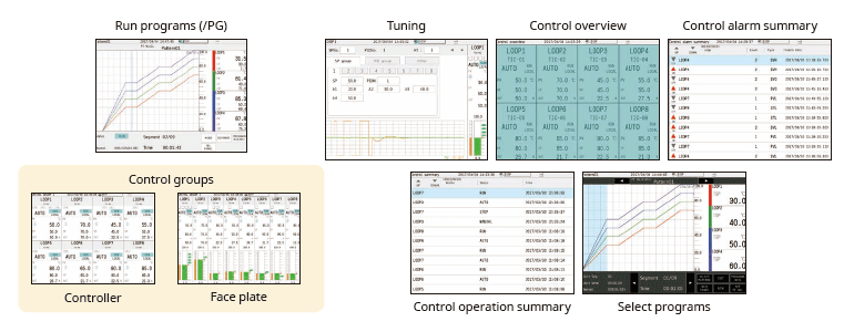
다양하고 편리한 PID 제어
PID및 프로그램 컨트롤
- PID 컨트롤 모듈
모듈 당 2-루프, 최대 20 루프 - Set 포인트 프로그램 제어 기능 (/PG 옵션)
최대 99 패턴

웹브라우저를 통한 실시간 원격 모니터링
웹 브라우저를 통해 GP를 실시간으로 모니터링하고 설정을 변경할 수 있습니다. 추가 소프트웨어 없이도 손쉽게 비용이 적게 드는 원활한 원격 모니터링 시스템을 구축할 수 있습니다.
실시간 모니터링 스크린
GP 메인 장치에서 트렌드, 디지털 및 기타 디스플레이와 동일한 모니터 화면을 실시간으로 볼 수 있습니다.

*웹브라우저에서 Java 플러그인이 동작 중인 SMARTDAC+ 시리즈
웹브라우저 온라인 세팅
설정화면을 통해 AI채널 설정 등을 엑셀로 복사하여 편집할 수 있으며, 편집 후 설정화면으로 데이터를 다시 가져올 수 있습니다.

GX/GP 설정 및 파형 뷰어 전용 소프트웨어 (무료 Download)
Universal viewer
GX/GP에 저장된 데이터 파일을 보고 인쇄할 수 있습니다. 영역에 대한 통계 계산을 수행하고 ASCII, Excel 또는 다른 형식으로 내보낼 수 있습니다.

Offline setting software
설정을 저정하거나 저장된 내용을 GX/GP 로 보낼 수 있습니다.

열처리 응용을 위해 항공우주 산업의 AMS2750/NADCAP 및 자동차 산업의 CQI-9를 지원
리브레이션 보정 스케줄 제어 기능 (/AH 옵션)
캘리브레이션 보정 등을 주기적으로 실행하기 위한 일정 관리, 단위 및 센서 의존성에 대한 보정 계수를 별도로 설정할 수 있으며, AMS2750의 경우 TUS(온도 분포 테스트) 보고서를 쉽게 작성할 수 있는 TUS 소프트웨어*를 제공합니다.*
* TUS 소프트웨어에 대한 상세는Yokogawa 영업 담당자와 상담하세요.

설비 세트 당 별도의 파일로 레코더 데이터 저장
멀티-배치 기능 (/BT 옵션)
독립적인 시작 및 중지 제어로 데이터 파일을 분리하기 위해 사전 정의된 채널 그룹을 기록합니다. 최대 12개의 독립 배치를 만들 수 있습니다.

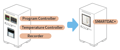
끊김없는 데이터 누적
복잡한 제어 패널을 단순하고 유연한 데이터 수집 스테이션에 결합하고 통합합니다.
고속 측정 (최속 1 ms)
Yokogawa의 독자적인 A/D 컨버터는 고속 모듈이 1ms의 빠른 데이터 포인트를 측정할 수 있도록 합니다.
- 고속 (1 ms) 측정*
- 독자적인 A/D 컨버터
*With 1ch per module. At 2 ms, 2 ch per module, and at 5 ms or more, all 4 ch per module.
| Model | Scan interval | ||
|---|---|---|---|
| 1ms | 2ms | 10ms | |
| GP10 | 1ch | 5ch | 10ch |
| GP20-1 | 1ch | 5ch | 10ch |
| GP20-2 | 5ch | 25ch | 40ch |

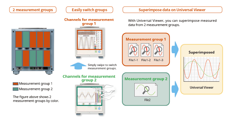
두 개의 서로 다른 스캔 인터벌을 사용한 듀얼 인터벌
사용자는 단일 GX/GP 시스템에서 두 개의 서로 다른 스캔 인터벌을 선택할 수 있는 기능이 있습니다. 이를 통해 사용자는 단일 시스템에서 두 개의 서로 다른 스캔 인터벌로 다양한 유형의 입력에 대해 유연하게 대응 할 수 있습니다. 예를 들어, 온도와 같은 느린 변화 와 압력, 진동과 같이 빠르게 변화하는 신호의 효율적인 동시 측정을 제공합니다. 모듈은 측정 그룹 할당으로 인터벌을 각각 설정할 수 있습니다.
MATH (레포트 포함), 이벤트 션
MATH 기능 (/MT 옵션)
기본적인 수학 및 함수(제곱근, 로그, 삼각법)를 포함한 다양한 종류의 수학 계산을 지원합니다. 측정 또는 계산된 데이터에 대한 변수를 사용하여 공식을 작성하고 결과를 저장 또는 표시합니다. 이를 통해 후처리에 대한 시간과 노력을 절약할 수 있습니다. Report(레포트) 기능을 사용하여 시간별, 일별, 월별 및 기타 보고서를 만듭니다
이벤트 액션
데이터 수집 스테이션의 작동 중에 특정 이벤트에 연결된 작업을 할당할 수 있는 기능입니다.

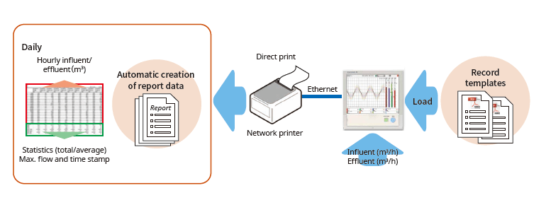
레포트 작성 및 네트워크 기능 (/MT 옵션)
어떤 템플릿으로도 자동으로 레포트를 작성
임의로 작성한 양식 템플릿을 GP의 내부 메모리에 읽어오면 Excel 또는 PDF 형식의 보고서가 자동으로 생성되며 LAN 연결을 통해 프린터로 출력할 수도 있습니다.
다양하고 편리한 네트워킹 기능 제공
모드버스/TCP, 모드버스/RTU 통신
GP는 이더넷 통신을 위해 Modbus TCP/IP 클라이언트 및 서버 모드를 지원하고 선택적 직렬 통신을 위해 Modbus RTU 마스터 및 슬레이브 모드를 지원합니다.
모드버스/TCP (이더넷 접속)
Modbus/TCP 및 Modbus/RTU 기능을 사용하여 GP의 서버 및 슬레이브 장치에서 데이터를 표시하고 저장할 수 있습니다.
* 통신 채널 필요 (/MC 옵션)

모드버스 RTU (RS-422A/485 접속)
모드버스/TCP 와 모드버스/RTU 기능을 사용하여 GP의 데이터를 상위 설비에서 취득할 수 있습니다.

(최대 16개의 모드버스/TCP 서버와 접속 가능, GP20-2의 경우 32개까지 가능)
(최대 31개의 모드버스/RTU 슬레이브와 접속 가능)
EtherNet/IP Function (/E1 option)
EtherNet/IP 서버 기능을 사용하여 PLC 또는 다른 장치에서 GX에 액세스하여 측정/연산 채널을 읽고 통신 입력 채널에 쓸 수 있습니다(GX10: 최대 500ch, GX20-1: 최대 300ch, GX20-2: 최대 500ch). 통신 채널 기능(/MC 옵션)이 필요합니다.
또한 배치 프로세스에 필요한 다음 작업은 명시적 메시지를 사용하여 PLC를 통해 수행할 수 있습니다.
참고: OMRON PLC에서 명시적인 메시지 작업이 확인되지 않았습니다.


PROFINET 통신 (GX90NW Network 모듈)
GX90NW 네트워크 모듈을 사용하여 PROFINET을 통해 보조 I/O 장치로 GX/GP를 연결할 수 있으며, PLC 또는 기타 I/O 컨트롤러에서 GX/GP에 액세스하여 측정/산술 채널을 읽고 통신 채널에 쓸 수 있습니다.
* PLC에서 Batch 프로세스에 필요한 작업을 쉽게 수행할 수 있습니다.

장치 성능 평가 테스트를 위한 강력한 Tool (/E2 와 /MC 옵션)
전력 측정 기기(WT series power analyzer)에서 정밀도가 높은 측정 데이터를 GP에 대한 충실도 손실 없이 획득할 수 있으며, GX 자체 측정 데이터와 함께 기록 및 표시할 수 있습니다. 이는 기기 전력 소모, 온도 및 기타 현상을 동시에 기록할 수 있기 때문에 성능 평가 테스트에 이상적입니다.
- 접속 가능 모델:
Yokogawa Test & Measurement Corp.,
WT series power analyzers,
WT300/WT300E (command mode WT300), WT500, WT1800/WT1800E (command type WT1800) - 최대 접속 수: 8 (GP10), 16 (GP20)

OPC-UA Server (/E3 옵션)
GP에 의해 획득된 데이터는 호스트 시스템(OPC-UA 클라이언트)으로부터 이더넷 통신을 통해 액세스될 수 있습니다. 업스트림 시스템으로부터 GP 통신 채널로 쓰기 위해서는 통신 채널 기능(/MC 옵션)이 필요합니다.

DARWIN-호환 통신
GX는 DARWIN 통신 명령을 지원합니다. GP에서 현재의 DARWIN 통신 프로그램을 그대로 사용할 수 있습니다.*
* 자세한 내용은 대리점 또는 가장 가까운 Yokogawa 대리점에 문의하십시오.
CENTUM/STARDOM 통신 패키지
- CENTUM: LFS2432, DARWIN/DAQSTATION Communication package (for ALE111 [Ethernet])
- STARDOM: NT365AJ DARWIN connection package

FTP-기반 파일 전송
FTP 클라이언트/서버 기능을 사용하면 중앙 파일 서버에서 데이터를 쉽게 공유하고 관리할 수 있습니다.

E-mail 메시지 전송 기능
알람 발생 정보, 예약 순시값, 보고서 데이터 등을 이메일로 전송합니다.

자동 네트워크 설정 (DHCP) 기능
Dynamic Host Configuration Protocol (DHCP)을 사용하여, 혜에 자동으로 (IP address) 설정을 할 수 있습니다. 이를 통해 공장 네트워크에 장치를 설치하는 것이 그 어느 때보다 쉬워집니다.

네트워크 시간 서버를 통한 시간 동기화
GP는 클라이언트 모드에서 SNTP 프로토콜을 사용하여 네트워크 타임 서버로부터 시간 정보를 획득합니다. 이 기능은 시설 내의 임의의 수의 GP 유닛이 정확하게 동기화된 시간을 가질 수 있도록 합니다. 모든 유닛은 조정된 날짜 및 타임 스탬프 정보와 함께 데이터를 기록합니다. 또한 GP는 서버로서 기능하여 네트워크의 다른 SNTP 클라이언트 유닛에 시간 데이터를 제공할 수 있습니다.

견고한 하드웨어와 높은 보안성
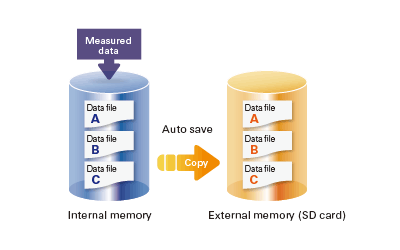
확고하게 저장된 데이터
측정 및 계산된 데이터는 보안 내장 비휘발성 메모리에 지속적으로 저장됩니다. 수동 또는 예약 간격으로 메모리의 파일을 이동식 미디어에 복사합니다. 또한 파일을 복사하여 FTP 서버에 보관할 수 있습니다.
비휘발성 메모리의 고유한 신뢰성과 보안 때문에 작동 조건이나 정전 이벤트에서 데이터가 손실될 가능성은 매우 적습니다.
어플리케이션에 대한 파일 형식 선택
보안을 강화하기 위해 측정된 데이터를 Binary 형식으로 저장할 수 있습니다. 이 형식은 기존 텍스트 편집기 또는 다른 프로그램에서 해독하거나 수정하기가 매우 어렵습니다. 텍스트 편집기 또는 스프레드시트 프로그램에서 데이터를 쉽고 직접 열 수 있도록 하려면 텍스트 형식을 선택하십시오. 이를 통해 전용 소프트웨어 없이도 측정 데이터를 사용할 수 있습니다.

보안성 강화
고객 데이터의 안전한 송수신

SSL: TCP/IP 네트워크 상 데이터 송수신을 위한 보안 프로토콜
전면 패널 도어 잠금 장치
전면 패널 도어를 잠글 수 있으므로 전원 스위치 또는 외부 미디어의 잘못된 취급 및 접근을 방지할 수 있습니다.

아날로그 front end 모듈
전용 A/D 컨버터를 통해 고속, 고정밀 데이터 수집(High Speed AI, PID Control 모듈)

Standards supported
GX는 CSA, UL, CE/EMC 지침/CE/정전압 지침, 유럽 RoHS 지침, WEEE 지침, RCM, KC Mark(한국) 등 다양한 표준을 지원합니다

엄격한 데이터 보안 대응
Advanced security function 옵션 (/ AS)을 통해 엄격한 데이터 관리 요구 사항에 대응
SMARTDAC+ GX/GP/GM Advanced Security 옵션(/AS)은 의약품 제조, 생명공학, 건강 관리 및 의료 기관과 같은 응용 분야에서 안전하고 추적 가능한 데이터 관리를 제공합니다.
고급 보안 기능은 데이터 관리를 위한 미국 FDA 21 CFR Part 11, EU-GMP Annex 11 및 기타 관련 지침의 엄격한 요구 사항을 지원합니다.
또한 PIC/S, WHO, MHRA 및 FDA 지침 문서에 언급된 ALCOA+(속성, 판독 가능, 현대적, 원본, 정확, 완료, 일관성, 지속성, 가용성)에 따라 데이터 무결성을 지원합니다.
"ALCOA +"?
A: 귀속성(attribution), L: 가독성(Legibility), C: 동시성(simultaneity), O: 독창성(Originality), A: 정확성(Accuracy), C: 완전성(Completeness), C: 일관성(Consistency), E: 지속성(Oresistence), A: 가용성(Availability)을 의미합니다. ALCOA +는 PIC / S (의약품 시험 계약 및 의약품 시험 공동 체계), WHO (세계보건기구), MHRA (의약품 및 의약품 규제 당국: 영국), FDA (식품의약품청)의 데이터 무결성 가이드라인 요건입니다.
디지털 기록 데이터 보안
측정된 데이터, 설정 및 작업 로그가 하나의 인코딩된 이진 파일에 저장됩니다. 이진 형식의 인코딩된 데이터는 대부분의 텍스트 편집기에서 열 수 없으므로 높은 수준의 보안을 제공합니다.
데이터 파일이 손상되거나 변조된 경우 SMARTDAC+ Standard Universal Viewer 소프트웨어가 부적합 사항을 식별하고 이에 따라 사용자에게 알립니다.
보안성이 확보된 파일 및 데이터 전송
SMARTDAC+는 FTP 서버에 자동으로 데이터를 전송할 수 있으며, SSL을 사용하여 FTP를 통해 전송되는 데이터를 암호화하는 FTPS도 지원되어 데이터 파일을 안전하게 전송할 수 있습니다.

전자 서명(데이터 레코드 사인)기능
측정 데이터는 GX/GP(내부 메모리에 있는 데이터만 해당) 또는 SMARTDAC+ Standard Universal Viewer 소프트웨어에 표시 및 확인이 가능하며, 해당 데이터에 전자 서명을 적용할 수 있습니다. 서명은 운영자, 관리자, 품질 관리의 세 가지 수준이 있으며, 서명은 합격/불합격, 주석 등의 정보와 함께 데이터에 저장하여 검토 및 감사할 수 있습니다.
*GM에 대한 전자서명은 SMARTDAC+ Standard Software에서만 가능하며, GM의 웹서버를 통해 전자서명을 신청할 수 없습니다.

로직 보안
데이터 무결성을 위해서는 올바른 사용자가 올바른 정보에 액세스할 수 있어야 합니다.
SMARTDAC+는 다양한 액세스 권한을 가진 사용자를 생성할 수 있습니다.
- 4가지 주요 보안 수준(사용자 및 모니터 사용자의 두 가지 별도 관리자 역할)
- 최대 200명까지 등록할 수 있습니다.
- 프로세스 소유자/시스템 소유자에게는 자신의 역할에 적합한 기능에 대한 액세스 권한이 부여될 수 있습니다.
- 암호의 경우 최소 문자열 길이와 최소 정책 복잡도를 설정할 수 있습니다.
- Active Directory를 통해 네트워크의 서버를 사용하여 사용자 이름과 암호를 중앙 집중식으로 관리할 수 있습니다.

Audit 추적 기능
SMARTDAC+ 의 동작 로그는 측정 데이터와 함께 파일에 저장됩니다.
설정 변경 시 설정 변경 작업과 함께 변경 사유 기록이 가능하며, 또한 "설정 차이 작업 이력"에서 설정 변경 내역을 확인하면 감사 시 데이터 확인 작업이 크게 줄어듭니다.

무료 소프트웨어 제공
SMARTDAC+ Standard Software를 통해 측정 데이터 표시, 작업 로그 표시, GX/GP/GM 구성이 가능하며 SMARTDAC+ Standard Universal Viewer를 사용하여 데이터를 로그인할 수도 있습니다.
Universal Viewer software
Universal Viewer 소프트웨어는 파형, 수치 등 다양한 형태로 데이터 파일을 표시할 수 있으며, 측정 데이터뿐만 아니라 알람, 메시지 목록, 작업 로그 등을 표시하고 출력할 수 있으며, 작업 로그를 통해 변경 전 설정과 변경 후 설정을 비교하여 표시할 수 있어 자세한 변경 내용을 확인할 수 있습니다.
측정 데이터 확인 후 사용자 이름, 사용자 ID, 비밀번호를 입력하여 서명할 수도 있으며, 이미 서명이 완료된 데이터라면 화면에서 서명 상태를 확인한 후 다른 레벨로 서명할 수 있습니다.

Hardware Configurator software
Hardware Configurator 소프트웨어는 이더넷 통신뿐만 아니라 SD 메모리 또는 외부 저장 매체를 통해 가져올 수 있는 오프라인 시스템 구성을 허용합니다. 시스템 설정은 GX/GP/GM 시스템 유효성 검사(IQ/OP/PQ)를 지원하기 위해 테이블 형식으로 인쇄할 수 있습니다.
또한 선택한 설정 데이터 파일 페어를 비교할 수 있으며 그 차이를 테이블 형식으로 표시하고 인쇄할 수 있습니다.

Validation 문서
Validation 문서(별매)는 GX/GP/GM과 SMARTDAC+ Standard 시스템 Validation을 간소화한 Validation 프로토콜 템플릿으로, 편집이 용이하도록 Yokogawa 웹사이트에 MS Word 파일로 제공됩니다.*
*확인 및 문서 확인은 고객의 책임입니다.
-
List of Verified SD Memory Cards (SD Cards)
The SD cards of the following manufacturers have been verified for use with SMARTDAC+ GX/GP/GM, μR10000/μR20000 and FX1000. However, please note that Yokogawa does not guarantee normal operation of the SD card when using with products listed below.
-
【Support Information】List of Verified USB Barcode Reader
The USB barcode reader of the following manufacturers have been verified for use with the SMARTDAC+ GX/GP series, DXAdvanced series. However, please note that Yokogawa does not guarantee normal operation of the USB barcode reader when using with products listed below.
-
List of RoHS
This is a list of recorder and controller products that support the RoHS (2011/65/EU) directive.
-
New Legislative Framework (NLF) Conforming Products
This is a list of recorder and controller products that support the New Legislative Framework (NLF.)
-
【Support Information】Display Language Support List for Recorders
List of languages that can be set for each model.
자료실

Performing control while changing the set point temperature moment by moment is called running a program pattern (or simply running a program). Sterilization and pasteurization require maintaining specific temperatures for specific durations.

SMARTDAC+ GX series records the clean room temperature, humidity, atmospheric pressure, door openings and closings, etc.

- Universal inputs provide support for thermocouple, RTD, voltage, and a variety of other input signals.
- Lineup of models for up to 450 inputs.
Allows multipoint monitoring and recording on a single unit. - Easily enables network-based data management.
file transfers, Web monitoring, and alarm e-mail


AN 04L51B01-01EN

AN 04L51B01-02EN

AN 04L51B01-03EN

Multi-touch technologies have rapidly moved from the commercial to the industrial sector where they are being used to enhance data analysis.

Yokogawa Electric began offering the environmental monitoring system "OpreX Environmental Monitoring System" (hereinafter, OpreX EMS) for the pharmaceutical and medical device industries in October 2020. OpreX EMS, which was launched simultaneously domestically and overseas, is based on customers' needs, such as regulatory compliance, diversification of operational risks, and high usability. When asking the person in charge about the development history and features of the product, it was found that it is a new solution that meets the company's business vision.
Downloads
Instruction Manuals
- Precaution on the use of SMARTDAC+ (664 KB)
- Model GX10/GX20/GP10/GP20 Paperless Recorder First Step Guide (20.9 MB)
- Model GX10/GX20/GP10/GP20 Paperless Recorder User’s Manual (14.7 MB)
- Model GX10/GX20/GP10/GP20/GM10 Communication Command User's Manual (3.6 MB)
- Handling of the SD Memory Card (321 KB)
- SMARTDAC+ STANDARD Hardware Configurator User's Manual (4.4 MB)
- SMARTDAC+ STANDARD Universal Viewer User's Manual (4.2 MB)
- DXA170 DAQStudio User's Manual (4.8 MB)
- Cloud Equipment/Quality Predictive Detection Tool User’s Manual (166 KB)
- Regarding the Downloading and Installing for the Software, Manuals and Labels/About the Usage of Open Source Software (367 KB)
- Model GX10/GX20/GP10/GP20 Advanced Security Function (/AS) User’s Manual (4.9 MB)
- Model 773230 Downloading the Validation Documents (132 KB)
- Model GX10/GX20/GP10/GP20/GM10 Multi-batch Function (/BT) User’s Manual (3.5 MB)
- Model GX10/GX20/GP10/GP20/GM10 EtherNet/IP Communication (/E1) User’s Manual (1.8 MB)
- Model GX10/GX20/GP10/GP20/GM10 WT Communication (/E2) User’s Manual (1.5 MB)
- Model GX10/GX20/GP10/GP20/GM10 OPC-UA Server (/E3) User’s Manual (884 KB)
- Model GX20/GP20/GM10, UT52A/UT32A, UPM100 920 MHz Wireless Communication, MH920 Console International (For the US and the Korea) (12.0 MB)
- Model GX10/GX20/GP10/GP20/GM10 SLMP Communication (/E4) User's Manual (2.1 MB)
- Model GX10/GX20/GP10/GP20/GM10 Log Scale (/LG) User’s Manual (1011 KB)
- Model GX10/GX20/GP10/GP20/GM10 Loop Control Function, Program Control Function (/PG Option) User’s Manual (24.3 MB)
- Notes on using the Model GX90EX expansion module (I/O expansion module) (194 KB)
General Specifications
- GP10/GP20 Paperless Recorder (Portable Type) (3.9 MB)
- GX60 I/O Base Unit (Expandable I/O), GX90EX Expansion Module (3.1 MB)
- GX90XA/GX90XD/GX90YD/GX90WD/GX90XP/GX90YA I/O Modules (4.6 MB)
- GX90UT PID Control Module, GX10/GX20/GP10/GP20, GM, Loop Control Function, Program Control function (/PG) (1.8 MB)
- Equipment/Quality Predictive Detection Tool (340 KB)
- Model 773230 Validation Document for SMARTDAC+ (for the /AS option) (355 KB)
- 415940, 415941 and 415942 Shunt Resistor for Screw Input Terminal (178 KB)
- 438920, 438921 and 438922 Shunt Resistor for Clamp Input Terminal (252 KB)
- List of the US Toxic Substances Control Act (TSCA) Compliant Recorder and Controller Products (176 KB)
- List of RoHS (2011/65/EU) Directive Compliant Products (6-substances RoHS compliant products) (356 KB)
- New Legislative Framework (NLF) Conforming Products (362 KB)
Software
- Hardware Configurator *Log-in Required
- Universal Viewer *Log-in Required
- GA10 Data Logging Software *Log-in Required
- GA10 Data Logging Software [60-day free trial] *Log-in Required
- DAQStudio (DXA170) Revision Upgrade *Log-in Required
- Offline version: Equipment/Quality Predictive Detection tool OE10 *Log-in Required
- Validation Document for SMARTDAC+ *Log-in Required
- EtherNet/IP Profile (EDS file) for GX/GP *Log-in Required
- PLC Communication Protocol Profile (EDS file) for GX/GP (For connecting OMRON's PLCs) *Log-in Required
- SMARTDAC+ Report Template Builder *Log-in Required
- SMARTDAC+ Excel Report Simulator *Log-in Required
- SMARTDAC+ SettingFileConverter Settings File Conversion Tool *Log-in Required
- Tag Plate *Log-in Required
- Mobile WEB Application for GX/GP/GM *Log-in Required
- SD Card Formatter *Log-in Required
- LabVIEW Driver (for SMARTDAC+ Series) *Log-in Required
- GX/GP Firmware *Log-in Required
- SMARTDAC+ I/O Module Firmware *Log-in Required
- SMARTDAC+ I/O Expansion Module Firmware *Log-in Required
Technical Information
- Effectively Using SMARTDAC+; Software Introduction (6.1 MB)
- SMARTDAC+ Advanced Security Functions White Paper for FDA 21 CFR Part 11 (587 KB)
- Reduce Risk by Eliminating Paper Chart Records (1.6 MB)
- GX/GP Custom Display Setup Guide (642 KB)
- Recorders, Data Loggers, and Control Products Security Standard (488 KB)
- SMARTDAC+ Loop Control Function, Program Control Function (/PG Option) (9.5 MB)
- DARWIN Replacement Guide (9.1 MB)
- High-speed Measurement Application High-speed Measurement/ Dual Interval Measurement Feature LR Replacement (8.9 MB)
Drawings
- Paperless Recorder GP10 (913 KB)
- Paperless Recorder GP20 (1.0 MB)
- Expandable I/O GX60 (575 KB)
- Analog Input Module GX90XA (531 KB)
- Expansion Module GX90EX (207 KB)
- Digital Input/Output Module GX90WD (229 KB)
- Digital Input Module GX90XD (378 KB)
- Pulse Input Module GX90XP (329 KB)
- Analog Output Module GX90YA (265 KB)
- Digital Output Module GX90YD (267 KB)
동영상

Smart user interface, smart architecture, and smart functionality is achieved in the new Yokogawa SMARTDAC+ data acquisition and control product series. The Yokogawa SMARTDAC+ GX and GP are fully integrated measurement, display, and recording platforms equipped with an advanced touch screen operator interface. GX series is a panel-mount design, capable of operating in harsh industrial applications and environments. GP is the portable version of the GX, intended for use in lab and test bench applications.

This short video introduces SMARTDAC+ GX20 Data Acquisition Station and demonstrates how quickly we can set the unit up to do measurement and data recording.

This short video shows the method of adding input/output modules to the Yokogawa SMARTDAC+ Data Acquisition recording system and how to confirm correct installation.

This short video shows the method of configuring alarms on the SMARTDAC+ paperless recorder. In this example setting a high alarm on channel 1 at 25 Deg C.

This short video shows the method of configuring group settings in SMARTDAC+ paperless recorder.

This short video shows the method of loading a configuration file stored on an SD card into a SMARTDAC+ paperless recorder.

This short video shows the method of configuring tag numbers in the SMARTDAC+ paperless recorder.

This video shows the capability of viewing information from the 21 CFR Part 11 compliant SMARTDAC+ paparless recorder range on an iOS or Android device
기술 및 솔루션, 요꼬가와에 대한 자세한 정보를 찾고 계십니까?
견적 및 기술문의