By Lee Hamlett
Industries striving to improve control of their processes understand that high-quality measurement plays a key role in success. Communicating accurate and reliable measurements quickly to the controller is the goal. No matter the quality of the process control system or the cloud-based data collection, profit-saving results are impossible without accurate, reliable process data.
 Nowhere is that more true than with liquid tank level measurement (Figure 1). Incorrect levels can introduce problems that impact a plant’s bottom line. If the level is too high, the tank could overflow and lead to product loss, safety hazards, environmental issues or all three. If the level is too low, the pumps could burn out and increase maintenance costs. And, in general, an incorrect reading produces errors in inventory control and loss of potential returns on investment.
Many technologies are available to obtain accurate level readings, but the most widely used technology is differential pressure (DP). The easy-to-understand DP principle is field-proven, can provide cost advantages over other technologies and is ideal for many applications.
Unfortunately, the accuracy of DP level measurement has a pervasive enemy — temperature. As temperature changes, it impacts a measurement’s consistency and repeatability. The good news is that various solutions can reduce the impact of temperature on DP level applications. Some are standard and easy but help only a little. Other solutions require extensive engineering and maintenance. Still, others lie in the sweet spot where innovative solutions are both easy and effective.
HOW TEMPERATURE AFFECTS DP LEVEL MEASUREMENT
 DP level measurement works by inferring the level in the tank from the differential pressure that is measured. Accurate quantification requires DP and liquid density. Therefore, the media measured in the tank must have a constant density, or specific gravity (SG), to use the DP method.
The DP transmitter is installed at the bottom of the tank. The liquid in the tank creates pressure that is higher than the reference pressure. Therefore, as the level increases or decreases, there is a corresponding pressure change. For example, if the transmitter uses an analog 4-20 mA signal, the 4 mA signal corresponds to the pressure when the tank is empty (0% full), and the 20 mA signal corresponds to the pressure when the tank is 100% full.
The reference pressure varies by tank design (Figure 2). For example, an open tank is vented to the atmosphere and uses atmospheric pressure as the reference. In a closed or pressurized tank, the reference is the pressure measured at the top of the tank.
In the closed-tank system, the low-pressure side of the transmitter is connected to the top of the tank. Several methods, such as wet legs and dry legs, can make this connection. One of the most common connection methods uses remote seals or “chemical” seals attached via capillaries. The capillaries are filled with a fluid that transfers the pressure to the transmitter sensor. This connection eliminates corrosion, heat, and maintenance issues encountered in other connection methods.
In this type of installation, the DP transmitter measures media pressure in the tank, the pressure in the top of the tank, and the head pressure generated by the fill fluid in the capillary. The head pressure generated by the fill fluid is just like the transmitter measuring the level in a tank, but the tank is always at 100% full.
All smart pressure transmitters on the market can account for capillary head pressure. However, because there is a minimal amount of fill fluid in a very long tube, it can be affected by temperature. Like all liquids, a temperature change can cause a change in density (SG), causing the head pressure measured by the transmitter to change. As noted before, the DP method requires the density to be stable.
This temperature effect can originate from a variety of sources. For example, it can come from the high-pressure side capillary being shorter than the low-pressure side capillary, the high-side and low-side seeing different temperatures, or capillaries being too long. Each of these can be corrected with a well-designed system.

IMPROVE MEASUREMENT ACCURACY BY TRACKING THREE CONDITIONS
Generally, issues related to temperature are caused by variations in three conditions related to the capillaries. Innovative solutions lead to accurate readings.
 Capillaries of different lengths. The industry has found various methods to account for errors generated when capillaries are of different lengths. The difference in volumes of fill fluid causes different errors in each capillary (Figure 3). The longer capillary is affected by temperature more than the shorter capillary. The longer capillary has a larger fill fluid volume and expands or contracts more with temperature changes. The difference in fill fluid volumes causes an imbalance between the high-side and low-side pressure measurements.
Avoid the errors by balancing the capillary volumes in one of two ways. The first method is to make both capillaries the same length. This allows each capillary to sense the same temperature with the same fill fluid volume. Be mindful, however, that if the extra capillary length is found near the bottom of the tank, it could experience different temperatures than the capillary running to the top of the tank.
The second method requires a bit of engineering work upfront. Keep the capillaries at different lengths but change the internal diameter of the capillaries or the size of the seal diaphragm to ensure both capillaries have a similar volume of fluid. At its simplest, this task is a volume calculation. However, engineering teams often need guidance from the manufacturer. If they choose to implement this solution, they must avoid the condition in which capillaries are exposed to different temperatures.
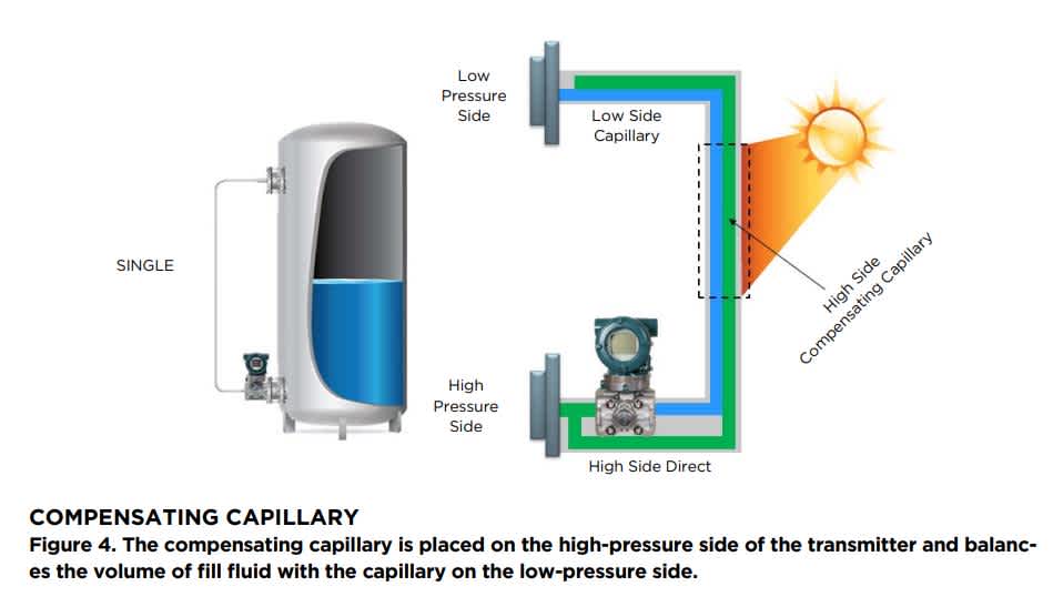
A difference in temperatures at the process connections. Temperature differences between the two process connections on the tank are common in tank farms. Tank farms are designed to pack as many tanks into as small a footprint as possible. This layout can lead to the exposure of capillaries to shade or sunlight, resulting in a noticeable temperature difference between the two. As described in the previous solution, the level measurement system must be designed to allow process connections and capillaries to sense the same temperature.
The solution is to add a reference capillary to the system. A compensating or reference capillary (Figure 4) is attached to the high-pressure side and bundled to run along the low-pressure-side capillary. This reference capillary experiences the same temperature as the low-side capillary and transfers the same effect to the high side.
As a result, the two capillaries and the reference capillary reach temperature equilibrium, eliminating the temperature imbalance. This solution also eliminates the capillary fill-fluid volume imbalance related to capillaries of different lengths.
Long capillaries. The longer the capillaries, the more temperature affects the system. Long capillaries are used, for example, on tall distillation towers and evaporators. Although the methods noted above can reduce the effect, the capillary length can become too long for these methods. In addition, the measured level becomes unusable because of inaccuracies.
The solution is deceptively simple: Eliminate the capillaries. Several companies on the market offer systems that replace the capillaries with wires or digital remote sensors connected by a bus. These systems each use two pressure sensors, one located at the high-pressure connection and another at the low-pressure side. If the two sensors communicate via electrical wiring, the wiring is not affected by temperature. The sensor located at the high-pressure process connector uses the information from the other sensor to generate an output signal for the level.
As a team considers this solution, the engineers must remember that although this system might cost a bit more initially, it makes up for the two-transmitter price in maintenance and installation. In addition, accuracy is good, but as the static pressure of the two-transmitter system increases, the accuracy is more difficult to achieve. Then, it is better to use a capillary solution. For example, it is easy to measure 5 inH2O and 3 inH2O and calculate a 2 in H2O differential. But if conditions present 100.072 psi and 100.000 psi, calculating the same 2 inH2O pressure difference is less accurate.
IMPROVED TANK LEVEL MEASUREMENT
Innovative solutions in the application of DP measurement technology offer reliable and accurate tank level measurements. For example, many companies have improved tank level measurements using a diaphragm seal system with a unique, compensating capillary or digital remote sensors specifically to address the temperature issues.
With improved accuracy and reduced variability in tank measurements, operators can increase chemical storage capacity and better manage production targets. In addition, manual checks are not required to confirm tank levels and periodically re-zero the transmitter. As a result, operators experience less process downtime, fewer inventory management problems, and improved environmental and safety compliance. More information can be found in this application note.
Regardless of the source of potential temperature challenges — capillaries of different lengths, the difference in temperatures on connections or long capillaries — users have found that a well-designed solution can reduce adverse effects. A discussion with the solution provider can reveal more about how to overcome temperature challenges with creative uses of technology and experience.

Related Industries
-
Chemical
Chemical plants rely on continuous and batch production processes, each posing different requirements for a control system. A continuous process calls for a robust and stable control system that will not fail and cause the shutdown of a production line, whereas the emphasis with a batch process is on having a control system that allows great flexibility in making adjustments to formulas, procedures, and the like. Both kinds of systems need to be managed in available quality history of product, and to be able to execute non-routine operations. With its extensive product portfolio, experienced systems engineers, and global sales and service network, Yokogawa has a solution for every plant process.
Related Products & Solutions
-
Diaphragm Seal System
Protect transmitters’ pressure-sensing assemblies with field-proven diaphragm seal solutions.
-
Differential Pressure Transmitters
Monitor and communicate pressure measurements with traditional mount or remote diaphragm seal mount transmitters.
-
EJA110E
High-Performance Differential Pressure Transmitter
-
EJA120E
Draft Range Differential Pressure Transmitter
-
EJA130E
Differential Pressure Transmitter
-
EJX118A
Differential Pressure Transmitter with Remote Diaphragm Seals
-
EJX120A
Traditional-Mount Draft Range Pressure Transmitter
-
EJX130A
High Static Differential Pressure Transmitter
-
EJXC40A (DRS)
Digital Remote Sensor (DRS) Transmitter
-
EJXC80A, EJAC80E (Differential / Gauge Pressure Diaphragm Seal)
Differential / Gauge Pressure Diaphragm Seal System with one or two Diaphragm Seals
-
EJXC80A, EJAC80E (Differential Pressure Direct Mounted Seal)
Differential Pressure Direct Mounted Seal
-
EJXC81A, EJAC81E (Absolute Pressure Diaphragm Seal)
Absolute Pressure Diaphragm Seal System
-
Pressure Transmitters
Deliver high reliability across a range of process conditions
Have Questions?
Contact a Yokogawa Expert to learn how we can help you solve your challenges.