
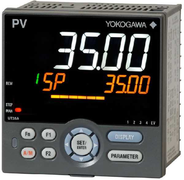
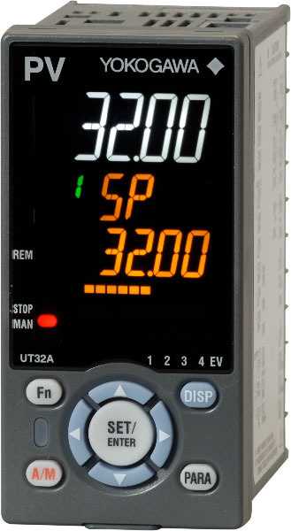

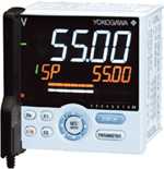
The UT35A and UT32A temperature controllers employ an easy-to-read, 14-segment large color LCD display, along with navigation keys, thus greatly increasing the monitoring and operating capabilities. A ladder sequence function is included as standard. The short depth of the controller helps save instrument panel space. The UT35A/UT32A also support open networks such as Ethernet communication.
UT35A and UT32A Temperature Controller Features
- 4 target setpoints (PID numbers) available as standard
- 3 alarm independent common terminals available as standard
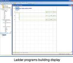
- Ladder sequence programs can be built
- Simple operation
- Up to 8 DOs (combinations available)
- Multiple language operation manual (Japanese, English, German, French, Spanish, Chinese and Korean) available. Please specify the desired language when ordering.
- Detailed code model available to customize specifications best suited to you.
Details
8 Built-in Control Modes
The control mode allows easily configuring settings and making changes with parameters.
- Single-loop control
- Cascade primary-loop control
- Cascade secondary-loop control
- Cascade control
- Loop control for backup
- Loop control with PV switching
- Loop control with PV auto-selector
- Control with PV-hold function
8 Built-in Control Types
- PID control
- ON/OFF control (1 point of hysteresis)
- ON/OFF control (2 points of hysteresis)
- Two-position, two-level control
- Heating/cooling control
- Sample PI control
- Batch PID control
- Feedforward control
For the correspondence between the above control mode and control types for each model, please refer to the specifications of each model.
Ladder Sequence Control
With built-in ladder sequence control, the range of applications are dramatically increased. This feature is standard in all the UTAdvanced controllers (except UM33A). The ladder sequence control function can replace a small PLC required by the application. Sequence control and PID control can be performed simultaneously.
- Monitoring and control of external machinery
E.g.: Lamps, switches, timers - Solve digital input/output logic functionality easily.
Number of basic command types: 13
Number of application command types: 73
| [Example of ladder instruction] | [Example of ladder programming] |
 |
|
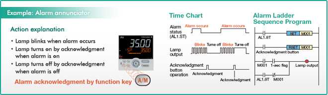
Application Examples of Ladder Sequence Program
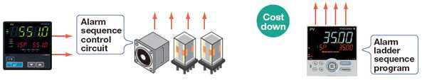
Alarm Sequence Control Circuits Can be Reduced
The ladder sequence program is built in the UTAdvanced as standard. The ladder sequence function enables monitoring and controlling peripheral devices such as relays, thus making it possible to reduce costs.
|
[Conventional] |
 |
[UTAdvanced] Alarm action is built by the ladder sequence program inside the UTAdvanced, thus making it possible to reduce costs. |
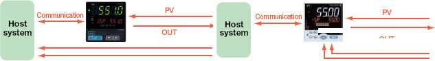
Host System Load is Reduced
|
[Conventional] |
[UTAdvanced] The UTAdvanced with up to 4 analog inputs* enables various types of analog data to be captured directly into the controller and calculated by the ladder program, thus reducing the system-building load of the host. Action: Various types of analog data were captured into the host system (PLC, etc.) and calculated, and the results were processed by the field controller for control via a command. * In the case of the UT55A |

Universal Input/Output
Select Input and Output Types via Configuration
Universal Input
Select from TC, RTD, mV/DC voltage and DC current. (DC current input: No shunt resistor required)
The input type and range is user selectable via the front panel or by using the LL50A parameter setting software.
 ±0.1% Indication Accuracy.
- Connect up to two 2-wire transmitters simultaneously.
All instruments have a 15 V Loop Power Supply (15 V LPS) for a transmitter.
In addition, a 24 V LPS is also available simultaneously for some instruments as optional function.
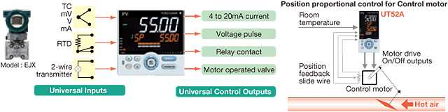
Universal Output
User selectable for relay, Voltage pulse and current outputs.
- Relay output: ON/OFF control, time-proportional PID control
- Voltage pulse output: time-proportional PID control
- Current output: continuous PID control
Heating/cooling control has two sets of universal outputs.
- Any combinations of relay, pulse and current outputs are available.
Drive a motorized control valve by using position-proportional PID.
- The position-proportional PID control function has two sets of relay outputs for direct/reverse rotation of motorized control valve.
- The slide wire input to feed back the valve position is also available.
Auto-tuning (AT) Function
The following conditions can be set in order to increase the accuracy of calculating PID constants using AT .
- Two types of algorithms to calculate PID constants are available for selection.
Normal: fast-rising PID constant
Stable: slow-rising PID constant - High and low output limits can be set individually for control output values during AT runtime.
SUPER Function Suppresses Overshoot
The field proven SUPER function utilizes a built-in operator experience and fuzzy theory to deliver fine control and suppress overshoot.

SUPER2 Function Suppresses Hunting
The new SUPER2 function utilizes a built-in operator experience and modern control theory to deliver fine control and suppress hunting.
LL50A Parameters Setting Software
Parameter Setting/Program Pattern Creating Function
Parameters that determine controller functions can easily be set: controller model type, controller mode (single-loop control, cascade control, loop control with PV switching, etc.), universal input/output functions, setup parameters and others. It also allows you to create program patterns.

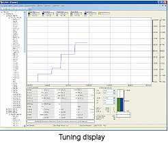
Tuning Function
Used to tune a controller's PID parameters. Displays measured input value, target setpoint, and control output value as a trend graph on a personal computer screen, allowing PID parameter modification, AUTO/MAN switching, control output modification in manual operation, etc.
Ladder Building Functions
Ladder sequence programs can be created and ladder programs can be monitored.
Network Profile Creation Function
Can be used to create an electronic device data sheet for Open Network.
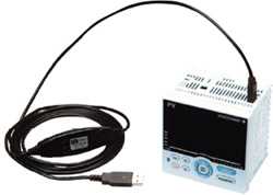
Via Bus Powered USB Cable
Can be set parameters and ladder program while no power supply to controller.
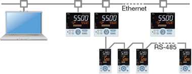
Via Ethernet Communication Connector
Via Dedicated Adapter
 Can be used while attached to the control panel.
- Applicable Termperature Controllers: UT55A, UT52A, UT35A, UT32A, UP55A, UP35A, UM33A
- Applicable OS: Windows XP/Vista
- Communication method: USB 1.1
Via RS-485 Communication Terminals

Bright & Easy to Read Active Color LCD Display

Versatile Color LCD Display

Operation Displays of the Program Controller
| SP Display | Program Pattern Display | Remaining Segment-time Display | Remaining Repetition Display |
 |
 overview |
 |
 |
| TSP Display | Program Pattern Display | Segment Number Display | |
 |
 Soak and ramp |
 |
|
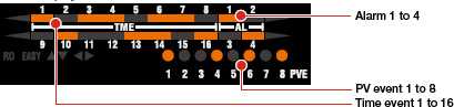
| Event Display | |||
 |
|||
 * The same operation displays as those of the UT are also available.
Functions of the Program Controller
Fast-forwarding of program operation
Use this function when checking the program pattern setting. Only times of segments and time events can be faster.
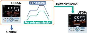
Program pattern-2 retransmission
The controller can serve as a program pattern generator.
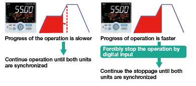
Synchronized program operation
If the progress of the operation of one unit is faster, the program operation can be forcibly stopped by digital input when switching between segments. Thus, synchronized program operation can be performed.
Optimal Display
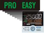 The controller menus and layout are adjusted in accordance with the level (EASY, STD, PRO) of information required by the user. If simple temperature or level control is needed, then select the easy configuration. Very sophisticated applications are no problem for the UTAdvanced. Just select the PRO setting and make use of the additional functionality shown in this mode. Advanced applications can be programmed in the PRO setting and then changed back to the easy setting to lock out functions not required by operators.
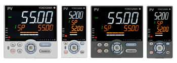
Active Color LCD Display
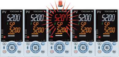 With Yokogawa's Active color display you can instantly tell, at a glance, the status of your process.
Alarm Status: Active color display changes from white (normal) to red (alarm).
Deviation Status: Color changes based on a PV deviation from SP.
User-defined Color: Choose between white or red display for constant Readings.
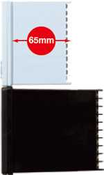
Compact Design
The 65-mm depth of the controller reduces the constraints on installation location.
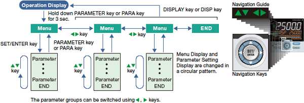
Easy Operation Map, Navigation Guide and Navigation Keys
The navigation keys is an intuitive method to navigate the controller's configuration menus and setting its various menus. Navigation arrows even tell you what button to push next.
Programmable Function Keys
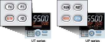 It is easy to assign frequently used functions, such as the operation mode switch, Run/Stop, program pattern selection, Remote/Local, alarm latch release, and PID parameter display. The function of an external switch can also be assigned to the front panel key in conjunction with a ladder sequence program.
Scrolling Text
The UTAdvanced is equipped with a scrolling text feature that fully lists the parameter being modified. There is no guessing what parameter you are looking at. It is possible to turn off scrolling the text function.
Multiple Language Support

The UTAdvanced is fluent in multiple languages — English, Spanish, French, and German. The use of the UTAdvanced by local language operators is not an obstacle.
User Settable Default Values
 Parameter values (SP, P, I, D, ALM1, etc.) configured by the user can be stored in the controller as the default values. Even if a parameter set value is accidentally changed, it can be restored to the original value with a simple operation.
Now Available in Two Colors (White or Black)
Now you can choose a color that matches your work area: white (light gray), or black (light charcoal gray).
Parameter Setting
LL50A Parameter Setting Software (sold separately) allows for easily setting parameters.

Message Function
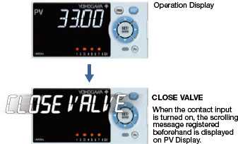 Using the message function and turning the contact input on/off, the message registered beforehand can be displayed on PV display by interrupt.The message is registered using LL50A Parameter Setting Software.The messages are limited to 20 alphanumeric characters. A maximum of four messages can be registered.
Quick Setting Function
Minimum parameters necessary for operation can be set.
Security Function
The password function can prevent inadvertent changes to the parameter settings. If a password is set, the password is required when moving to the Setup Parameter Setting Display. When the password is verified, can be changed to the Setup Parameter Setting Display.
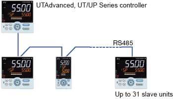
Communication Functions
A simple and easy network connection is provided!
A built-in function in the controller eliminates the need for a converter and makes wiring simple.
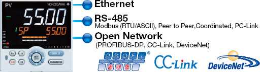
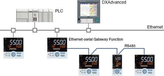
Modbus/TCP
Modbus TCP/IP, a protocol that allows the controller to connect to any Ethernet network and have the ability to exchange data with the computers or devices on that network.
- Allows control devices to be integrated into an application simply.
- Works with any Modbus TCP/IP compliant software.
- Support for Modbus function codes 03, 06, 08 & 16.
- Gateway function allows RS-485 Modbus devices to communicate via Ethernet.
- Reduced labor costs in wiring and setup of a communications network.
- Physical Layer: 10 BASE-T/100 BASE-TX
- Maximum number of connection: 2
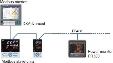
Modbus/RTU
The data of UTAdvanced (slave units) can be displayed and saved on the DXAdvanced using the Modbus RTU function.
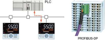
Open Network (PROFIBUS-DP, CC-Link, DeviceNet)
Embedded open networks will provide direct connection to PLC's.
- Reads data from UTAdvanced
- Writes parameter setting value to UTAdvanced
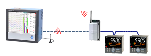
920 MHz band wireless communication (option)
The addition of a 920 MHz wireless function to the UT52A/MDL and UT32A/MDL enables wireless data communication with the GX20 paperless recorder or GM10 data acquisition system (/CM2 option) as the remote I/O. It can also be used as a repeater.
RS485 communication. Up to 31 connected slaves with a maximum length of 0.7 miles.
Peer to Peer
The use of the ladder sequence program makes it possible to exchange analog data and status data between communication-capable UTAdvanced.
Example: A UTAdvanced in which an input error occurs sends a signal to another UTAdvanced to enable that UTAdvanced switch to MAN operation, thus shifting the whole system into a safe mode. In such a case, the safety mechanism can be built into the UTAdvanced and is not required in the host system.

Coordinated Operation
In coordinated operation, a single UTAdvanced termperature controller is used as a master controller and multiple UTAdvanced or other UTAdvanced digital indicating controllers as slave controllers.
The slave controllers are operated in accordance with the actions of the master controller.
PC-Link
A protocol used for communicating with a general-purpose personal computer, or UTAdvanced series link module and serial communication module of FA-M3R (range-free controller).

Dependable 3 year warranty*1

Backed by the high reliability and quality that Yokogawa has cultivated over many years.
RoHS/WEEE compliant
UTAdvanced is environmentally safe when disposing.
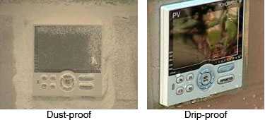
Dust-proof and drip-proof front panel (NEMA4*2 /IP66)
UTAdvanced can also be used for food-processing equipment with washable control panels.
- The 3 year warranty extends 36 months after shipment from our factory.
- Hose down test only.
| ITEM | UT35A | UT32A | |
|---|---|---|---|
| PV input | Input type | 1 Universal input (TC, RTD, mV, V, mA) | |
| Indication accuracy | ±0.1% of F.S. | ||
| Control scan period | 200 msec | ||
| PV/SP data display | 14-segment, 5 digits, Bar graph LCD display | ||
| Control outputs (MV) | Type | Relay, Voltage Pulse, Current | |
| Algorithm | ON/OFF, PID (Continuous, Time-proportional), Heating/Cooling, Position-proportional | ||
| Digital inputs | Number | 2 (Std) 7 (Max) | 2 (Std) 4 (Max) |
| Type | SP No.Change, PID No. Change, A/M Change, etc | ||
| Digital outputs | Number | 3 (Std) 8 (Max) | 3 (Std) 5 (Max) |
| Function | PV High, PV Low, Dev High, etc | ||
| Current trans input (option) | Number | 2 | |
| Retransmission | Number | 1 | |
| Type | PV, SP, OUT, etc | ||
| Remote (aux.) input (option) | Number | - | - |
| Type | - | ||
| Loop power supply (LPS) (option) | Number | 1 | |
| Voltage | 21.6 to 28.0 VDC | ||
| Communication (option) | Number | 1 | 1 |
| Type | RS-485, Ethernet, PROFIBUS-DP, CC-Link, DeviceNet | RS-485 | |
| Other specifications | Power supply | 100 to 240 VAC (+10%, -15%) or 24 VAC/DC (+10%, -15%) (option) | |
| Power consumption | Max 18 VA | Max 15 VA | |
| Mass | Max 0.5 kg | ||
Comparison Chart (UT75A/UT55A/UT52A/UT35A/UT32A)
 |
 |
 |
 |
 |
|||
| Model | UT75A | UT55A | UT52A | UT35A | UT32A | ||
|---|---|---|---|---|---|---|---|
| Size | 1/4 DIN | ✓ | ✓ | ✓ | |||
| 1/8 DIN | ✓ | ✓ | |||||
| Depth from the panel surface (mm) | 65 | 65 | 65 | 65 | 65 | ||
| Number of Control loops | Standard (Maximum) | 1(2) | 1 | 1 | 1 | 1 | |
| Control Scan Period | (msec) | Choice 50/100/200 | Choice 50/100/200 | Choice 50/100/200 | 200 | 200 | |
| Display Function | Number of PV Display Digits | 5 | 5 | 5 | 5 | 5 | |
| Active Color PV Display Function | ✓ | ✓ | ✓ | ✓ | ✓ | ||
| Guide Scroll Display Function | ✓ | ✓ | ✓ | ✓ | ✓ | ||
| Message Display Function | ✓ | ✓ | ✓ | ✓ | ✓ | ||
| Bar graph display (Number) | ✓(2) | ✓(2) | ✓(2) | ✓(1) | ✓(1) | ||
| PV Input Indication Accuracy | (% of F.S.) | 0.1 | 0.1 | 0.1 | 0.1 | 0.1 | |
| PV Input Type | TC | ✓ | ✓ | ✓ | ✓ | ✓ | |
| RTD (3-wire) | ✓ | ✓ | ✓ | ✓ | ✓ | ||
| RTD (4-wire) | ✓ | ✓ | ✓ | ||||
| mV, V | ✓ | ✓ | ✓ | ✓ | ✓ | ||
| mA | ✓ | ✓ | ✓ | ✓ | ✓ | ||
| Number of Analog Inputs | Standard (Maximum) | 1(4) | 1(4) | 1(2) | 1 | 1 | |
| Number of SPs (PIDs) | Maximum | 20(16) | 8 | 8 | 4 | 4 | |
| Number of Control Modes | Maximum | 9 | 8 | 8 | 1 | 1 | |
| Number of Control Types | Maximum | 8 | 8 | 8 | 5 | 5 | |
| Control Output | Type | Relay Contact Output, Voltage pulse output, Current output | ✓ | ✓ | ✓ | ✓ | ✓ |
| Algorithm | ON/OFF | ✓ | ✓ | ✓ | ✓ | ✓ | |
| PID (Continuance, Time Proportion) | ✓ | ✓ | ✓ | ✓ | ✓ | ||
| Position proportional | ✓ | ✓ | ✓ | ✓ | ✓ | ||
| Heating/cooling | ✓ | ✓ | ✓ | ✓ | ✓ | ||
| Number of Analog Outputs | Standard (Maximum) | 2(3) | 2(3) | 2(3) | 2 | 2 | |
| Number of Digital Inputs | Standard (Maximum) | 3(8) | 3(9) | 3(5) | 2(7) | 2(4) | |
| Number of Alarms | 8 | 8 | 8 | 4 | 4 | ||
| Number of Digital Outputs | Standard (Maximum) | 3(8) | 3(18) | 3(5) | 3(8) | 3(5) | |
| Communication | RS-485 communication (Maximum) | ✓(2) | ✓(2) | ✓(1) | ✓(1) | ✓(1) | |
| Ethernet communication | ✓ | ✓ | ✓ | ||||
| Open Network (CC-Link/PROFIBUS-DP/DeviceNet) | ✓ | ✓ | ✓ | ||||
|
920 MHz band wireless communication |
✓ |
✓ |
|||||
| Various Function | Quick Setting Function | ✓ | ✓ | ✓ | ✓ | ✓ | |
| Split Computation Output Function | ✓ | ✓ | ✓ | ||||
| Ratio and Square Root Extraction Function | ✓ | ✓ | ✓ | ||||
| Remote SP Function | ✓ | ✓ | ✓ | ||||
| 24 V DC Loop Power Supply Function | ✓ | ✓ | ✓ | ✓ | |||
| Heater Break Alarm Function | ✓ (Standard type) |
✓ (Standard type) |
✓ (Standard type or Heating/ cooling type) |
✓ (Standard type or Heating/ cooling type) |
|||
| Ladder Sequence Function | (Number of max. steps) | ✓(1000) | ✓(500) | ✓(500) | ✓(300) | ✓(300) | |
| Other specifications | Power Supply | AC100 V to 240 V | ✓ | ✓ | ✓ | ✓ | ✓ |
| AC/DC 24 V | ✓ | ✓ | ✓ | ✓ | ✓ | ||
| Dust and waterproof Level of Front Panel | NEMA4 *1 (IP66) | NEMA4 *1 (IP66) | NEMA4 *1 (IP66) | NEMA4 *1 (IP66) | NEMA4 *1 (IP66) | ||
| Configuration Tool | Via Light-loader Communication | ✓ | ✓ | ✓ | ✓ | ✓ | |
| Via Maintenance Port Communication |
✓ | ✓ | ✓ | ✓ | ✓ | ||
| Via RS-485/Ethernet communication |
✓/✓ | ✓/✓ | ✓/- | ✓/✓ | ✓/- | ||
The table above includes specifications of the standard models only.
* 1: Hose down test only.
Input Range
| Input type | |
|---|---|
| TC | K, J, T, B, S, R, N, E, L, U, W PL-2, PR20-40, W97Re3-W75Re25 |
| RTD | JPt100, Pt100 |
| DC Voltage | 0.4 to 2.0 V, 1.0 to 5.0 V, 0.0 to 2.0 V, 0 to 10 V, -10 to 20 mV, 0 to 100 mV |
| DC Current | 4 to 20 mA, 0 to 20 mA |
-
List of RoHS
This is a list of recorder and controller products that support the RoHS (2011/65/EU) directive.
-
【Support Information】UTAdvanced Series Parameter Maps and Lists
UTAdvanced series Parameter map list for each model can be downloaded.
Please use it to manage and save the set parameters. Also please use it as a reference for the key operation at that time. -
New Legislative Framework (NLF) Conforming Products
This is a list of recorder and controller products that support the New Legislative Framework (NLF.)
Resources
Yokogawa's UPM100 Power Monitor provides overall factory power monitoring operations and the DX1000 Paperless Recorder for temperature recording in refining furnaces.

What happens when a freeze event threatens the cooling systems that keep data centers running? Discover how one OEM used Yokogawa's advanced control technology to detect problems before they became failures, improve system reliability, and maintain uptime in demanding data center environments.

The UTAdvanced Digital Indicating Controller comes standard with ladder sequence function. The ladder sequence function can handle measured and computed values from the controller. Using this function, the UTAdvanced converts outputs from other controllers such as YS1500 to time proportioning outputs.

This introduces a system that uses Ethernet communications to acquire measured values, target values, and control output values from a controller installed on site into a PLC at high speed (ten units' worth within one second).

Controls temperature in, and acquires data from, various internal components of plastic film manufacturing equipment. An easy to use, high cost-performance data acquisition and monitoring system can be assembled by using Ethernet compatible instruments and GA10.
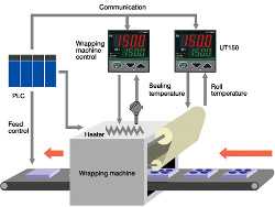
The TC series of temperature controllers is perfect for controlling the heating temperature of sealing parts and the temperature of sealing rolls (pre-heating) in a variety of different wrapping machinery.
Load devices are sometimes used when evaluating (measuring) DUT performance. Depending on the parameter being evaluated, multiple controllers can be employed to control the performance of the load device, but there are also times when the load device uses only one actuator.
In the plants of food and beverage manufacturers, there are times when monitoring and recording of production equipment is necessary inside clean rooms. This is an introduction to monitoring and recording in clean rooms using paperless recorders.
Downloads
Brochures
- Digital Indicating Controller UTAdvanced (4.8 MB)
- Digital Indicating Controllers [SUPPLEMENT] (156 KB)
- Digital Indicating Controller UTAdvanced for Customization (1.7 MB)
- SMART 920, 920 MHz band wireless communication instrument series (For US market only) (5.6 MB)
- UTAdvanced UT55A/UT52A/UT35A/UT32A Digital Indicating Controllers, Program Controllers UP55A/UP35A, Digital Indicator with Alarm (3.4 MB)
- Mining Solutions (3.2 MB)
- UTAdvanced UT55A/UT52A/UT35A/UT32A,UP55A/UP35A (Spanish) (1.1 MB)
- SMART 920 (4.0 MB)
- Nuclear Solutions – Data Acquisition, Control and Monitoring Solutions for Nuclear Power (13.3 MB)
Instruction Manuals
- Compliant with Safety and EMC Standard (376 KB)
- UT35A/MDL, UT32A/MDL Controller (DIN Rail Mounting Type) Operation Guide (1.6 MB)
- Precautions on the Use of the UTAdvanced Series (286 KB)
- UT32A-D Digital Indicating Controller (Dual-loop type) User's Manual (10.3 MB)
- UT32A-D Digital Indicating Controller (Dual-loop type) Operation Guide (3.9 MB)
- UT32A Digital Indicating Controller (Entry Model) User's Manual (5.0 MB)
- UT32A-D Digital Indicating Controller (Dual-loop, DIN Rail Mounting Type) Operation Guide (1.2 MB)
- UT35A/UT32A Digital Indicating Controller Operation Guide (for Standard code model) (3.6 MB)
- UT35A/UT32A Digital Indicating Controllers Operation Guide (for Detailed code model) (3.6 MB)
- UT35A/UT32A Digital Indicating Controller User's Manual (9.7 MB)
- UT52A/MDL, UT32A/MDL Digital Indicating Controller (DIN Rail Mounting and Wireless Communication Type) Operation Guide (US, KR) (1.1 MB)
- UTAdvanced Series Communication Interface (Open Network) User's Manual (6.5 MB)
- UTAdvanced Series Communication Interface (RS-485, Ethernet) User's Manual (8.1 MB)
- Model GX20/GP20/GM10, UT52A/UT32A, UPM100 920 MHz Wireless Communication, MH920 Console International (For the US and the Korea) (12.0 MB)
- UT32A Digital Indicating Controller (Entry Model) Operation Guide (3.7 MB)
- UTAP005 Wall Mount Bracket (964 KB)
- UT35A-L Digital Indicating Controller (Limit Control Type) Operation Guide (3.7 MB)
- UT35A/RSP, UT32A/RSP Digital Indicating Controller (with non-isolated remote input) Operation Guide (3.7 MB)
- UT32A Digital Indicating Controller (Entry Model) Operation Guide (3.6 MB)
- Control of Pollution Caused by the Product (258 KB)
- UT35A-L Digital Indicating Controller(Limit Control Type) User's Manual (8.3 MB)
- UT35A/UT32A Digital Indicating Controllers Operation Guide (Detailed code model) (Spanish) (7.9 MB)
- UTAdvanced Series - Notice of Alterations (136 KB)
General Specifications
- UT35A/MDL, UT32A/MDL Digital Indicating Controller (DIN Rail Mounting Type) (1.9 MB)
- UT35A, UT32A Digital Indicating Controller (Panel Mounting Type) (1.5 MB)
- UT32A Digital Indicating Controller (Entry model) (680 KB)
- UT32A-D/MDL Digital Indicating Controller (Dual-loop, DIN Rail Mounting Type) (905 KB)
- UT32A-D Digital Indicating Controller (Dual-loop, Panel Mounting Type) (802 KB)
- New Legislative Framework (NLF) Conforming Products (362 KB)
- List of RoHS (2011/65/EU) Directive Compliant Products (6-substances RoHS compliant products) (356 KB)
- UT52A/MDL, UT32A/MDL Digital Indicating Controller (DIN Rail Mounting and Wireless Communication Type) (1.4 MB)
- X010 External Precision Resistor (349 KB)
- UT35A/RSP, UT32A/RSP Digital Indicating Controller (with Non-isolated Remote Input) (1.2 MB)
Technical Information
- Digital Indicating Controllers Replacement Guide (9.1 MB)
- Recorders, Data Loggers, and Control Products Security Standard (488 KB)
- GREEN to UTAdvanced Conversion Tool Operation Guide (2.0 MB)
- UTAdvanced UT35A/UT32A Digital Indicating Controller Parameter Maps and Lists (660 KB)
- GREEN to UTAdvanced Model Conversion Table (289 KB)
- Setup Procedure UTAdvanced Quick Setting (Controlling Flow with Inverters) (325 KB)
- Setup Procedure UTAdvanced Quick Setting (Controlling Furnace Temperature with a Motorized Valve) (285 KB)
- Setup Procedure UTAdvanced Quick Setting (Controlling Furnace Temperature with a Solid State Relay) (296 KB)
- Setup Procedure UTAdvanced Quick Setting (Controlling Furnace Temperature with a Thyristor) (274 KB)
- Setup Procedure UTAdvanced Quick Setting (Controlling Heat Exchanger Temperature) (338 KB)
- Setup Procedure UTAdvanced Quick Setting (Controlling Tank Level ON-OFF) (333 KB)
- Setup Procedure UTAdvanced Quick Setting (Controlling Tank Level Proportion) (364 KB)
- Setup Procedure UTAdvanced Quick Setting (Controlling Tank Pressure) (380 KB)
- Setup Procedure UTAdvanced Quick Setting (Controlling Tank Temperature) (286 KB)
- Setup Procedure UTAdvanced Quick Setting (pH Control) (295 KB)
- UTAdvanced - Changing the Decimal Point Position of TC or RTD Inputs (349 KB)
- UTAdvanced – Initializing Forgotten Password on UT55A/52A/35A/32A (166 KB)
Engineering Tools
- Model UT32A Digital Indicating Controller (280 KB)
- Model UT35A Digital Indicating Controller (280 KB)
- Model UT32A/MDL Controller (Mount on DIN Rail) (235 KB)
- Model UT35A/MDL Controller (Mount on DIN Rail) (285 KB)
- Model UT32A Digital Indicating Controller (UT32A-NNN-xx-xx/x) (244 KB)
- Model UT35A Digital Indicating Controller (UT35A-NNN-xx-xx/x) (256 KB)
- UTAdvanced Model: UTAP001 Terminal Cover for 96 x 96 mm (167 KB)
- UTAdvanced Model: UTAP002 Terminal Cover for 48 x 96 mm (145 KB)
Videos
Looking for more information on our people, technology and solutions?
Contact Us