


Yokogawa Chart Recorder Paperless Technology
Power generation, process automation, and factory automation in manufacturing industries require rigorous, continuous monitoring in the control room. The GX series is Yokogawa's latest recorder offering for industrial automation.
SMARTDAC+ Touch Screen GX10/GX20 is a multi-point touch screen recorder that provides intuitive, human-centric design, web-enabled functionality, and scalable architecture. The Yokogawa GX20 also supports 920 MHz band wireless communication.
Custom Touch Screen Software
The GX series is an industry-first multi-point touch panel, to improve intuitive and smart operator control. Users can scroll, pan, zoom historical data, and even write freehand messages on its dust-proof and water-proof display. The Yokogawa GX series delivers industry-leading reliability and measurement accuracy. Its custom graphics accommodates application or process-specific displays, while a wide range of communication protocols guarantee compatibility with your network architecture. It's simple for operators to view and retrieve past data with automatic email and FTP notifications.
Smart User Interface
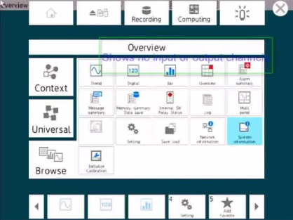
Variety of display functions
- Standard display screens clearly indicate channel data with units and tags, plus alarm log, message log, and other event log information.
- New Custom Display function (option) lets you place graphic images on screens.
Touch screen for intuitive operation
- The new touch screen provides swipe, pinch in/out, and click and drag controls for fast navigation of common display mode functions.
- Use "2-point touch" to zoom in or out in the direction of display span.
Supports freehand messages
- Operators can write a free hand text message directly on the touch screen with a stylus or finger.
Smart Architecture
Add I/O modules when you need more channels
- The fully modular I/O design allows you to build the system with the channels you need today, and expand the unit's capability any time in the future by purchasing and installing additional modules.
Wide-ranging input/output specifications
- The 10 channel universal input module measures DC volts, thermocouple, RTD, and contact input signals. A 16 channel digital input module and a relay output module are also available.
- GX90XA Analog input module: DC voltage, DC current, thermocouple, RTD, contact
- GX90XA-04-H0 High Speed AI Module:[R4] New! DC voltage, DC current, thermocouple, RTD, contact
- GX90XA-06-R1 4-Wire RTD Module:[R4] New! 4-wire RTD, 4-wire resistance
- GX90YA Analog output module:[R4] New! Current output (Isolated between channels)
- GX90XD Digital input module: Remote control input or operation recording
- GX90YD Digital output module: Alarm output
- GX90WD Digital input/output module: Remote control input or operation recording/alarm output
- GX90XP Pulse intput module: Pulse signal data acquisition, integral count
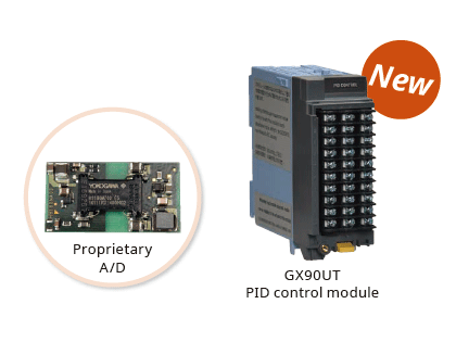
- GX90UT PID control module:[R4] New! PID control (2 loop)
Front panel door available in white or black
- Choose the best color for your operating environment.
Multichannel I/O
- GX10 and GX20 support up to 30 channels and 100 channels of input respectively.
- Up to 450 inputs available with an expansion unit that provides easy Ethernet connection to the recorder.
Smart Functionality
PID control [R4] New!
- Enables PID and program control (up to 20 loops per system)
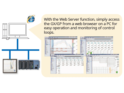
- The web application enables remote operation and monitoring from a browser.
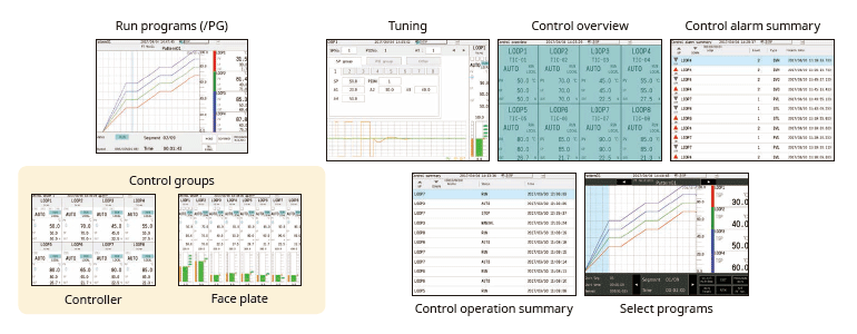
- Various pre-configured control screens and display are available.
- Setpoint program control function (up to 99 patterns)
Dual interval measurement [R4] New!
- Users have the ability to choose two different scan intervals on a single GX system.
920 MHz band wireless communication (option for GX20)
- Easily acquire and record data wirelessly from remote I/O GM10, UT32A or UT52A.
Direct output to printers
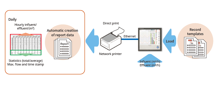
- You can print out reports and snapshots directly from the GX, without going through a PC.
Convenient report creation function
- Reports can be created automatically using a spreadsheet template created in Excel. You can also output to a PDF file.
Browser-based real time monitoring
- A web browser can be used to fully access the GX using two operating modes— Data and Configuration.
21 CFR Part 11 support (option)
- Supports the U.S. FDA 21 CFR Part 11 (for pharmaceutical manufacturing).
Easy connection with WT series powermeters (option)
- Easily acquire and record measured data from power measuring instruments (WT series, power analyzers).
DARWIN compatible functions (Ethernet, RS-422/485, RS-232)
- Upgrade smoothly from DARWIN data acquisition instruments.
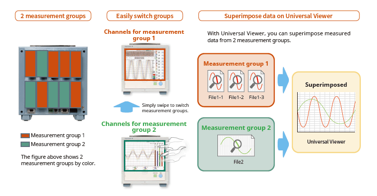
Multi-batch Function (option)
- Recorder pre-defined channel groups to separate data files with independent start and stop control.
SLMP Communication (Mitsubishi PLC) (option)
- Protocol function that enables connection from a GX to Mitsubishi Electric PLCs without sequence programs.
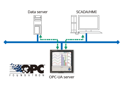
OPC-UA Server (option)
- Data acquired by the GX can be accessed through Ethernet communication from a host system (OPC-UA client).
Aerospace Heat Treatment Supports heat treatment application AMS2750/NADCAP
- Calibration correction schedule control function (option) Schedule management for periodically executing calibration correction configuration and the like.
Details
An intuitive UI engineered for ease-of-use
Efficiently search for key data
Easily review historical data
Seamless display of historical trends—flick or drag the trend display to scroll through the data, even during measurement.

Quickly find data using calendars and summary screens
From a calendar, jump to waveforms of a specific date. From the alarm summary, jump to the waveform active during the alarm.

Easily check off trouble spots
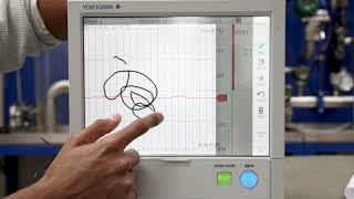
Write freehand messages
Immediately clear areas of concern with a hand-written message.

You can draw or hand-write on the waveform area using a stylus (standard accessory) or the tip of your finger. You can even select a color and line width. Alternatively, you can select from a list of preset messages.
Save and output image files
Save trend waveforms of interest or screens displayed during alarms as image (PNG) files, and print them out at the same time.

Check waveforms of concern in detail
Display digital values at any location
Move the scale to display the value corresponding to that position as a numeric value. Instantly check maximum/minimum measured values.

[Patent technology]
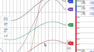
Ascertain long-duration trends at a glance
All historical trends display
Long-duration trends can be fitted to a single screen for easy viewing.

All historical trends display
Zoom in/out - time axis and engineering units
The time axis and engineering axis can expanded and compressed using a simple pinch together or apart function

Pinch apart / Pinch together
Create your own screens
Custom display (/CG option)
You can arrange display objects such as trend, numeric, and bar graphs any way you like to create monitor displays that are customized to the environment. Start/stop pumps and perform other operations.


Custom display building software
DAQStudio DXA170
DAQStudio is software for creating custom displays. You can load screens you created onto the GX via Ethernet or external memory media (SD/USB) and display them.

Variety of display screens
Physical quantities are displayed and recorded on a log scale.

Multi-panel display
You can select from 9 layouts, and save up to 20 configurations. (Multi panel available on the GX20 only)


Highly flexible and scalable architecture
Modular input/output
Inputs and outputs are modular for easy expandability. The GX multichannel paperless recorder main unit alone provides up to 100 channels (GX20) of measurement.

Wide variety of input/output modules
Select from a wide variety of input/output modules.

| Model | Name | Measurement/Application | Channels |
|---|---|---|---|
| GX90XA-10-U2 | Analog input module | DC voltage, DC current (with external shunt resistor connected), thermocouple, RTD, contact (solid state relay scanner type) | 10 |
| GX90XA-10-L1 | DC voltage, DC current (with external shunt resistor connected), thermocouple, contact (Low withstand voltage solid state relay scanner type) | 10 | |
| GX90XA-10-T1 | DC voltage, DC current (with external shunt resistor connected), thermocouple, contact (electromagnetic relay scanner type) | 10 | |
| GX90XA-10-C1 | DC current (mA) (solid state relay scanner type) | 10 | |
| GX90XA-04-H0 | DC voltage, DC current (with external shunt resistor connected), thermocouple, RTD, contact (individual A/D type) | 4 | |
| GX90XA-06-R1 | 4-wire RTD, 4-wire resistance (solid state relay scanner type) | 6 | |
| GX90YA | Analog output module | Current output | 4 |
| GX90XD | Digital input module | Remote control input or operation recording | 16 |
| GX90YD | Digital output module | Alarm output | 6 |
| GX90WD | Digital input/output module | Remote control input or operation recording/alarm output | DI:8/DO:6 |
| GX90XP | Pulse input module | Pulse signal data acquisition, integral count | 10 |
| GX90UT | PID control module | PID control (2 loop) | AI:2/AO:2 DI:8/DO:8 |
Expandable to up to 450 channels (real actual input)
Supports up to 450 channels of measurement. Note that if MATH and communication channels are included, the GX20 large memory type can record on up to 1000 channels. The GX main unit and expandable I/O can both use the same input/output modules.

You connect directly with a LAN cable without connecting through a hub or repeater.
* You can also connect subunits of the GM Data Acquisition System.
| Model | Type | Max.channels | Number of channels by configuration | |
|---|---|---|---|---|
| GX10 | Standard | 100ch | Main unit only | 0-30 |
| Main + expandable I/O | 0-100 | |||
| GX20 | Standard | 100ch | Main unit only | 0-100 |
| Main + expandable I/O | 0-100 | |||
| Large memory | 450ch | Main unit only | 0-100 | |
| Main + expandable I/O | 0-450 | |||
The number of channels is for analog input only.
Reduce wiring with distributed installation
When the recorder is installed offsite (away from the DUT), you can place the expandable I/O at the site and monitor data without the need for long-distance wiring of thermocouples and other sensors.

A full range of network functions and software
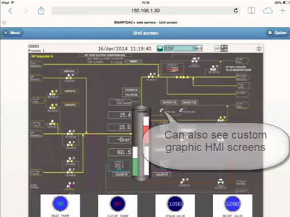
Real time remote monitoring from a web browser
Through a Web browser you can monitor the GX in real time and change settings. You can easily build a seamless, low-cost remote monitoring system with no additional software.
Real time monitoring screen
You can view monitor screens in real time that are identical to the trends, digital, and other displays on the GX main unit.

Enter settings online with a web browser
The setting screen lets you copy AI channel settings and other information to Excel for editing. You can reimport the data into the setting screen after editing.

Dedicated software (free download) is available for loading waveforms and GX settings.
Universal viewer
Data files saved on the GX can be viewed and printed. You can perform statistical computation over an area and export to ASCII, Excel, or other formats.

Offline setting software
Save settings or transfer them to the GX.

Aerospace Heat Treatment Supports heat treatment application AMS2750/NADCAP
Calibration correction schedule control function (/AH option)
Schedule management for periodically executing calibration correction configuration and the like. The correction factor can be set separately for unit and sensor dependency. TUS report software enables you to easily create TUS (temperature uniformity survey) reports.*.
* For information on TUS software, contact your Yokogawa representative.

Record data in separate files per equipment set
Multi-batch Function (/BT option)
Recorder pre-defined channel groups to separate data files with independent start and stop control. Up to 12 independent batches can be created.

PID control function
Control function
Enables PID and program control
- PID control module
2-loops per module, up to 20 loops per system/li> - Setpoint program control function (/PG option)
Up to 99 patterns
Remote operation and monitoring
The web application enables remote operation and monitoring from a browser.
Built in control screens and display
Various pre-configured control screens and display are available.
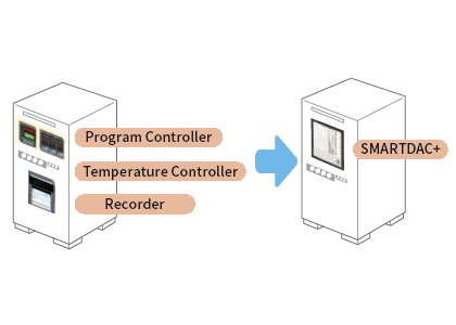
Seamless integration
Combine and integrate complex legacy control panel into a simple and flexible data acquisition station.
Custom display
Remote operation is possible through screens that are customized for your specific system.

High speed measurement (down to 1 ms)
Yokogawa's proprietary A/D converter allows the high speed module to measure data points as fast 1ms.
- High speed (1 ms) measurement*
- Proprietary A/D converter
With 1ch per module. At 2 ms, 2 ch per module, and at 5 ms or more, all 4 ch per module.

| Model | Scan interval | ||
|---|---|---|---|
| 1ms | 2ms | 10ms | |
| GX10 | 1ch | 5ch | 10ch |
| GX20-1 | 1ch | 5ch | 10ch |
| GX20-2 | 5ch | 25ch | 40ch |
Dual interval measurement with two different scan intervals
Users have the ability to choose two different scan intervals on a single GX/GP system. This allows users the flexibility to measure various types of inputs with two different scan intervals in a single system. For example, this provides for efficient, simultaneous measurement of signals with slow fluctuations such as temperature, and fast-changing signals such as pressure and vibration. Modules can be assigned to measurement groups.
MATH (including reports), and event actions
MATH function (/MT option)
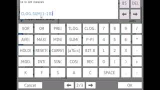
Supports various kinds of math computation, including basic math and functions (square root, logarithms, trigonometry). Write formulas using variables for measured or computed data and save or display the results—this saves time and effort on post-processing. Create hourly, daily, monthly, and other reports with the Report function.

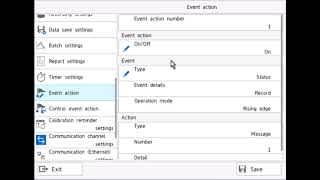
Event actions
Ability to assign actions tied to specific events during the operation of the data acquisition station.

Report creation and network functions (/MT option)
Provides a variety of convenient networking functions
Modbus/TCP and Modbus/RTU Communications
GX supports Modbus TCP/IP client and server modes for Ethernet communications and Modbus RTU master and slave modes for optional serial communications.
Modbus/TCP (Ethernet connection)
Using the Modbus/TCP and Modbus/RTU functions, you can display and save data from the server and slave devices on the GX.*
* Requires the communication channel (/MC option ).

(Connect up to 16 Modbus/TCP servers, or up to 32 for the GX20-2.)
(Up to 31 Modbus/RTU slaves can be connected.)
Modbus/RTU (RS-422/485 connection)
Using the Modbus/TCP and Modbus/RTU functions, you can acquire GX data from upstream devices.

EtherNet/IP Function (/E1 option)
GX supports EtherNet/IP server functions. You can access GX from PLCs or other devices and load measurement/MATH channels or write* to communication input channels (GX10: max. 50 ch, GX20-1: max. 300 ch, GX20-2: max. 500 ch).
* Requires the communication channel function (/MC option).

CC-Link family SLMP communication (/E4 option)
Protocol function that enables connection from a GX to Mitsubishi Electric PLCs without sequencer programs. You can run the GX as an SLMP client, enabling writing of GX measured data to the PLC and writing of PLC data to communication channels.*
*Requires the communication channel function (/MC option).

Powerful tool for instrument performance evaluation testing (/E2 and /MC options)
Highly precise measured data from power measuring instruments (WT series power analyzers) can be acquired without loss of fidelity on the GX, and recorded and displayed alongside the GX's own measured data. This is ideal for performance evaluation testing because you can record instrument power consumption, temperature, and other phenomena simultaneously.

- Models that can be connected:
Yokogawa Test & Measurement Corp.,
WT series power analyzers,
WT300/WT300E (command mode WT300), WT500, WT1800/WT1800E (command type WT1800) - Max. no. of connections:
8 (GX10), 16 (GX20)
OPC-UA Server (/E3 option)
Data acquired by the GX can be accessed through Ethernet communication from a host system (OPCUA client). Writing from an upstream system to a GX communication channel requires the communication channel function (/MC option).
DARWIN-compatible communication
The GX supports DARWIN communication commands. Use your current DARWIN communication programs as-is on the GX.*
* See your dealer or nearest Yokogawa representative for details.

CENTUM/STARDOM communciation package
- CENTUM: LFS2432, DARWIN/DAQSTATION Communication package (for ALE111 [Ethernet])
- STARDOM: NT365AJ DARWIN connection package
FTP-based file transfer
The FTP client/server functions allow you to easily share and manage data from a centralized file server.

E-mail messaging function

Automatic network setup (DHCP) function
Using Dynamic Host Configuration Protocol (DHCP), the GX can automatically acquire the settings it needs (IP address) for network communications from a DHCP server. This makes it easier than ever to install the unit on a plant network.
 function")
Time synchronization with network time servers
GX uses SNTP protocol in client mode to acquire time information from a network time-server. This function allows any number of GX units within a facility to have precisely synchronized time; all units will record data with coordinated date and time stamp information. In addition, GX can function as a server, providing time data to other SNTP client units on the network.

Rock-solid hardware and highly secure
Choice of mounting designs

Be confident that recorded data is saved
Measured and calculated data is continuously saved to secure, internal non-volatile memory. At manual or scheduled intervals, the files in memory are copied to the removable media. In addition, the files can be copied and archived to an FTP server.

Because of the inherent reliability and security of non-volatile memory, the possibility of losing data under any operating condition or power failure event is extremely small.
Select file formats according to your application
For increased security, measured data can be saved in binary format. This format is very difficult to decipher or modify in traditional text editors or other programs. To enable easy and direct opening of the data in text editors or spreadsheet programs, choose text format. This allows you to work with your measurement data without dedicated software.

ASCI data display

Binary data display
21 CFR Part 11 support (/AS option)
With the expanded security function option, the instruments support the USA FDA's Title 21 CFR Part 11 regulations (for the pharmaceutical manufacturing industry). It gives you access to a credential-based login function, electronic signatures, audit trails, an anti-tampering function, an Active Directory-based password management function, a sign-in function, and other security features.
")
Security enhancements
Safely sends and receives customer data.

SSL: An encryption protocol for data sent over TCP/IP networks.
Front panel door lock
The front panel door can be locked to prevent mishandling of the power switch or external media.

Analog front end module
A proprietary A/D converter delivers high speed, high precision data acquisition. (High-speed AI, PID Control module)

Standards supported

Analog input module

Specifications
| Model | GX90XA | ||||||||||||||||||||||||||||||||||||||||||||||||||||||||||||||||||||||||||||||||||||||||||||||||||||||||
|---|---|---|---|---|---|---|---|---|---|---|---|---|---|---|---|---|---|---|---|---|---|---|---|---|---|---|---|---|---|---|---|---|---|---|---|---|---|---|---|---|---|---|---|---|---|---|---|---|---|---|---|---|---|---|---|---|---|---|---|---|---|---|---|---|---|---|---|---|---|---|---|---|---|---|---|---|---|---|---|---|---|---|---|---|---|---|---|---|---|---|---|---|---|---|---|---|---|---|---|---|---|---|---|---|---|
| Input type (Inputs: 10) |
DC voltage*1, standardized signal*1, thermocouple*1, RTD*2, DI*1, DC current (with external shunt resistor)*1, DC current*3, resistance*4 | ||||||||||||||||||||||||||||||||||||||||||||||||||||||||||||||||||||||||||||||||||||||||||||||||||||||||
| DCV | 20 mV, 60 mV, 200 mV, 1 V, 2 V, 6 V, 20 V, 50 V, 100 V*5 | ||||||||||||||||||||||||||||||||||||||||||||||||||||||||||||||||||||||||||||||||||||||||||||||||||||||||
| Standard signal | 0.4-2 V, 1-5 V | ||||||||||||||||||||||||||||||||||||||||||||||||||||||||||||||||||||||||||||||||||||||||||||||||||||||||
| Resistance | 20, 200, 2000 Ω | ||||||||||||||||||||||||||||||||||||||||||||||||||||||||||||||||||||||||||||||||||||||||||||||||||||||||
| Thermocouple | R, S, B, K, E, J, T, N, W, L, U, W97Re3-W75Re25, KpvsAu7Fe, Platinel 2, PR20-40, NiNiMo, W/WRe26, N(AWG14), XK GOST | ||||||||||||||||||||||||||||||||||||||||||||||||||||||||||||||||||||||||||||||||||||||||||||||||||||||||
| RTD | Pt100, JPt100, Cu10 GE, Cu10 L&N, Cu10 WEED, Cu10 BAILEY, Cu10 (20°C) α=0.00392, Cu10 (20°C) α=0.00393, Cu25 (0°C) α=0.00425, Cu53 (0°C) α=0.00426035, Cu100 (0°C) α=0.00425, J263B, Ni100 (SAMA), Ni100 (DIN), Ni120, Pt25, Pt50, Pt200 WEED, Cu10 GOST, Cu50 GOST, Cu100 GOST, Pt46 GOST, Pt100 GOST, PT500*4, PT1000*4 | ||||||||||||||||||||||||||||||||||||||||||||||||||||||||||||||||||||||||||||||||||||||||||||||||||||||||
| DI | Level, Contact | ||||||||||||||||||||||||||||||||||||||||||||||||||||||||||||||||||||||||||||||||||||||||||||||||||||||||
| DC current | 0-20 mA, 4-20 mA | ||||||||||||||||||||||||||||||||||||||||||||||||||||||||||||||||||||||||||||||||||||||||||||||||||||||||
| Scan intervals |
1/2/5/10/20/50/100/200/500ms, 1/2/5s Scan interval by type
|
||||||||||||||||||||||||||||||||||||||||||||||||||||||||||||||||||||||||||||||||||||||||||||||||||||||||
| Power supply and consumption | Supplied from main unit, power consumption: 2 W or less | ||||||||||||||||||||||||||||||||||||||||||||||||||||||||||||||||||||||||||||||||||||||||||||||||||||||||
| Insulation resistance | Between input circuits and internal circuitry: 20 MΩ or greater (at 500 V DC) | ||||||||||||||||||||||||||||||||||||||||||||||||||||||||||||||||||||||||||||||||||||||||||||||||||||||||
| Withstand voltage | Between the input circuits and the internal circuitry: 3000 VAC for one minute (current input type and low withstand voltage type: 1500 VAC for one minute) Between analog input channels: 1000 V AC for one minute (excluding b terminals for universal input type) (low withstand voltage type: 400 VAC for one minute, high speed universal type: 3000 V AC for one minute) |
||||||||||||||||||||||||||||||||||||||||||||||||||||||||||||||||||||||||||||||||||||||||||||||||||||||||
| Terminal types | M3 screw terminals or clamp terminals | ||||||||||||||||||||||||||||||||||||||||||||||||||||||||||||||||||||||||||||||||||||||||||||||||||||||||
| Weight | Approx. 0.3 kg | ||||||||||||||||||||||||||||||||||||||||||||||||||||||||||||||||||||||||||||||||||||||||||||||||||||||||
*1 Cannot be set for the current input type (type suffix code: -C1) or 4-wire RTD/resistance type (type suffix code: -R1).
*2 Cannot be set for the current input type (type suffix code: -C1), electromagnetic relay type (type suffix code: -T1), or low withstand voltage type (type suffix code: -L1).
*3 Can only be set with current input type (type suffix code: -C1).
*4 Can only be set with 4-wire RTD/resistance type (type suffix code: -R1).
*5 Can only be set with high speed universal type (type suffix code: -H0).
Model and Suffix Codes
| Model | Suffix Code | Description | ||||
|---|---|---|---|---|---|---|
| GX90XA | Analog input module | |||||
| Number of channels | -04 | 4 channels (-H0 type only) | ||||
| -06 | 6 channels (-R1 type only) | |||||
| -10 | 10 channels | |||||
| Type | -C1 | Current, scanner type (isolated between channels) | ||||
| -L1 | Low withstand voltage DCV/TC/DI, scanner type (isolated between channels) | |||||
| -U2 | Universal, Solid state relay scanner type (3-wire RTD b-terminal common) | |||||
| -T1 | DCV/TC/DI, Electromagnetic relay scanner type (isolated between channels) | |||||
| -H0 | High speed universal, individual A/D type (isolated between channels) | |||||
| -R1 | 4-wire RTD/resistance, scanner type (isolated between channels) | |||||
| - | N | Always N | ||||
| Terminal form | -3 | Screw terminal (M3) | ||||
| -C | Clamp terminal | |||||
| Area | N | General | ||||
Analog output module

Specifications
| Model | GX90YA |
|---|---|
| Output type (outputs: 4) | Transmission output, manual output |
| Range | 4–20 mA or 0–20 mA |
| Output update interval | 100 msec (shortest) |
| Load resistance | 600 Ω or less |
| Resolution | 0.002% |
| Power supply and consumption | Supplied from main unit, power consumption: 3W or less |
| Insulation resistance | Between output circuits and internal circuitry: 20 MΩ (at 500 VDC) |
| Between output channel terminals: 500 VDC, 20 MΩ or greater | |
| Withstand voltage | Between output circuits and internal circuitry: 1500 AC for one minute |
| Between output circuits: 500 VAC for one minute | |
| Terminal type | M3 screw terminals or clamp terminals |
| Weight | Approximately 0.2 kg |
Model and Suffix Codes
| Model | Suffix Code | Description | ||||
|---|---|---|---|---|---|---|
| GX90YA | Analog output module | |||||
| Number of channels | -04 | 4 channels | ||||
| Type | -C1 | Current output (isolated between channels) | ||||
| - | N | Always N | ||||
| Terminal form | -3 | Screw terminal (M3) | ||||
| -C | Clamped terminals | |||||
| Area | N | General | ||||
Digital input module

Specifications
| Model | GX90XD | |
|---|---|---|
| Input types (Inputs: 16) |
DI or pulse input*1 (Open collector or non-voltage contact) | |
| ON/OFF detection | Open collector: Voltage of 0.5 V DC or less when ON, leakage current of 0.5 mA or less when OFF Non-voltage contact: Resistance of 200 Ω or less when ON, 50 kΩ when OFF |
|
| Contact rating | 12 V DC, 20 mA or more | |
| Power supply and consumption | Supplied from main unit, power consumption: 0.7 W or less | |
| Insulation resistance | Between input terminals and internal circuitry: 20 MΩ or greater (at 500 V DC) | |
| Withstand voltage | Between input terminals and internal circuitry: 1500 V AC for one minute | |
| Terminal types | M3 screw terminals or clamp terminals | |
| Weight | Approx. 0.3 kg | |
Pulse input specifications*1
| Counting system | The rising edge of the pulse is counted. |
|---|---|
| Max. pulse period | 250Hz (The chattering filter : OFF) 125Hz (The chattering filter : ON) |
| Minimum detection pulse width | Low (close), High (open), both is 2 ms or more |
| Pulse detection period | 1ms |
| Pulse measurement accuracy | ± 1 pulse |
| Pulse count interval | Measurement interval |
|
Filter |
The chattering filter can be switched On/Off. (When the chattering filter is off, connect GX/GP so that it is not affected by the noise.) |
*1 Integration requires the math function (optional code /MT).
Model and Suffix Codes
| Model | Suffix Code | Description | ||||
|---|---|---|---|---|---|---|
| GX90XD | Digital input module | |||||
| Number of channels | -16 | 16 channels | ||||
| Type | -11 | Open collector/Non-voltage, contact (shared common), Rated 5 VDC | ||||
| - | N | Always N | ||||
| Terminal form | -3 | Screw terminal (M3) | ||||
| -C | Clamp terminal | |||||
| Area | N | General | ||||
Digital output module

Specifications
| Model | GX90YD |
|---|---|
| Output types (outputs: 6) | Relay contact (c contact) |
| Rated load voltage | 100 to 240 V AC or 5 to 24 V DC |
| Max. load voltage/current | 264 VAC or 26.4 VDC, 3A/point (resistance load) |
| Power supply and consumption | Supplied from main unit, power consumption: 1.4 W or less |
| Insulation resistance | Between output terminals and internal circuitry: 20 MΩ (at 500 VDC) |
| Withstand voltage | Between output terminals and internal circuitry: 3000 V AC for one minute |
| Terminal types | M3 screw terminals |
| Weight | Approx. 0.3 kg |
Model and Suffix Codes
| Model | Suffix Code | Description | ||||
|---|---|---|---|---|---|---|
| GX90YD | Digital output module | |||||
| Number of channels | -06 | 6 channels | ||||
| Type | -11 | Relay, SPDT(NO-C-NC) | ||||
| - | N | Always N | ||||
| Terminal form | -3 | Screw terminal (M3) | ||||
| Area | N | General | ||||
Expansion module

Model and Suffix Codes
| Model | Suffix Code | Description | ||||
|---|---|---|---|---|---|---|
| GX90EX | I/O expansion module | |||||
| Port | -02 | 2 Ports | ||||
| Type | -TP1 | Twisted pair cable | ||||
| - | N | Always N | ||||
| Area | -N | Standard accessories | ||||
Digital input/output module

Specifications
| Model | GX90WD | |
|---|---|---|
| Input types (Inputs: 8) |
DI or pulse input*1 (Open collector or non-voltage contact) | |
| ON/OFF detection | Open collector : Voltage of 0.5 V DC or less when ON, leakage current of 0.5 mA or less when OFF Non-voltage contact : Resistance of 200 Ω or less when ON, 50 kΩ when OFF |
|
| Contact input rating | 12 VDC, 20 mA or more | |
| Output type (outputs: 6) | Relay contact (C contact) | |
| Rated load voltage | When connected to the main circuit (fi rst-order power supply), 150 VAC or less When connected to a circuit derived from the main circuit (second-order power supply), 250 VAC or less (the main circuit is 300 VAC or less and uses an isolated transformer) or 30 VDC or less |
|
| Max. load current | 2 A (DC)/2 A (AC), resistive load | |
| Power consumption | 1.9 W or less | |
| Insulation resistance | Between input terminals and internal circuitry: 20 MΩ or greater (at 500 VDC) Between output terminals and internal circuitry: 20 MΩ or greater (at 500 VDC) |
|
| Withstand voltage | Between input terminals and internal circuitry: 1500 VAC for one minute Between output terminals and internal circuitry: 3000 VAC for one minute |
|
| Terminal types | M3 screw terminals | |
| Weight | Approx. 0.3 kg | |
Each unit (GX/GP main unit and expandable I/O), can use 1 module only.
Pulse input specifications*1
| Counting system | The rising edge of the pulse is counted. |
|---|---|
| Max. pulse period | 250Hz (The chattering filter : OFF) 125Hz (The chattering filter : ON) |
| Minimum detection pulse width | Low (close), High (open), both is 2 ms or more |
| Pulse detection period | 1ms |
| Pulse measurement accuracy | ± 1 pulse |
| Pulse count interval | Measurement interval |
|
Filter |
The chattering filter can be switched On/Off. (When the chattering filter is off, connect GX/GP so that it is not affected by the noise.) |
*1 Integration requires the math function (optional code /MT).
Model and Suffix Codes
| Model | Suffix Code | Description | ||||
|---|---|---|---|---|---|---|
| GX90WD | Digital input/output module | |||||
| Number of channels | -0806 | 8 channel DIs, 6 channel DOs | ||||
| Type | -01 | Open collector/non-voltage contact (shared common), rated 5 VDC; Relay, SPDT, (NO-C-NC) | ||||
| - | N | Always N | ||||
| Terminal form | -3 | Screw terminal (M3) | ||||
| Area | N | General | ||||
Pulse input module

Specifications
| Model | GX90XP |
|---|---|
| Number of inputs | 10 |
| Measurement interval | 100 ms (shortest) |
| Input type | Contact (open collector, voltage-free contact), level (5 V logic) |
| Input range | Up to 20 kHz* * 30 Hz when the chattering filter is in use (On) |
| Minimum detection pulse width | 25 μs* * 15 ms when the chattering filter is in use (On) |
| Measurement accuracy | Count ± 1 pulse During integration, the following accuracies are added. Upon MATH start: +1 measuring period Upon MATH stop: -1 measuring period * Integration requires the math function (optional code /MT). |
| Chattering filter | Removes chattering up to 5 ms (can be turned on/off on each channel) |
| Hysteresis width | Approx. 0.2 V |
| Contact, transistor rating | Contact: 15 V DC or higher and 30 mA or higher rating. Minimum applicable load current 1 mA or less. Transistor: With the following ratings: Vce > 15 VDC, Ic > 30 mA |
| Maximum input voltage | ±10 V DC |
| Insulation resistance | Between input terminals and internal circuitry: 20 MΩ or greater at 500 V DC |
| Withstand voltage | Between input terminals and internal circuitry: 1500 V AC for 1 minute |
Model and Suffix Codes
| Model | Suffix code | Description | ||||
|---|---|---|---|---|---|---|
| GX90XP | Pulse input module | |||||
| Number of channels | -10 | 10 channels | ||||
| Type | -11 | DC voltage/open collector/non-voltage contact (shared common), rated 5 VDC | ||||
| — | N | Always N | ||||
| Terminal form | -3 | Screw terminal (M3) | ||||
| -C | Clamp terminal | |||||
| Area | N | General | ||||
PID control module

Specifications
| Model | GX90UT | |
|---|---|---|
| Control loops | Number of loops | 2 |
| Analog input (measured input) | Measured points | 2 |
| Measurement type | DC voltage (DCV)/standardized signal, TC/RTD, DI (LEVEL and non-voltage contact)/DC current (with external shunt resistance) | |
| Scan (control) interval | 100 ms or 200 ms (system global setting) | |
| Analog output (control output/transmission output/sensor power supply) | Outputs | 2 |
| Output type | Power supply for current, voltage pulse, or sensors. | |
| Current output: 4-20 mA or 0-20 mA | ||
| Voltage pulse output: ON voltage = 12 VDC or more (load resistance 600 Ω or more), OFF voltage = 0.1 VDC or less | ||
| Can be used as a sensor power supply (13.0-18.3 VDC) | ||
| Digital input (switching the SP, operation mode, etc.) | Inputs | 8 |
| Input format | Non-voltage contact and open collector | |
| Contact rating: 12 VDC or more, 20 mA or more | ||
| Digital output (of alarms, events, etc.) | Outputs | 8 |
| Output format | Open collector (sink type) | |
| Output contact capacity | Max 24 VDC, 50 mA | |
| Withstand voltage/insulation resistance | See PID control module general specifications (GS 04L51B01-31EN) | |
| Terminal type | M3 screw terminals | |
| Weight | Approximately 0.3kg | |
Model and Suffix Codes
| Model | Suffix Code | Description | ||||
|---|---|---|---|---|---|---|
| GX90UT | PID control module | |||||
| Number of loops | -02 | 2 loops | ||||
| Type | -11 | 8 DIs, 8 DOs | ||||
| — | N | Always N | ||||
| Terminal form | -3 | Screw terminals (M3) | ||||
| Area | N | General | ||||
as of March, 2017
The SD cards of the following manufacturers have been verified for use with SMARTDAC+® GX/GP/GM, µR10000™/µR20000™ and FX1000™. However, please note that Yokogawa does not guarantee normal operation of the SD card when using with products listed below.
SMARTDAC+ GX
Applicable Models: GX10, GX20, GX20W
SMARTDAC+ GP
Applicable Models: GP10, GP20
SMARTDAC+ GM
Applicable Models: GM10
| Manufacturer | Capacity | Manufacturer Model | GX10 | GX20 | GP10 | GP20 | GX20W | GM10 |
|---|---|---|---|---|---|---|---|---|
| SanDisk | 16GB | SDSDXS-016G | √ | √ | √ | √ | √ | |
| SanDisk | 8GB | SDSDXS-008G | √ | √ | √ | √ | √ | |
| SanDisk | 32GB | SDSDXVE-032G | √ | √ | √ | √ | √ | √ |
| SanDisk | 32GB | SDSDXS-032G | √ | √ | √ | √ | √ | √ |
| SanDisk | 32GB | SDSDXL-032G | √ | √ | √ | √ | √ | √ |
| SanDisk | 16GB | SDSDXL-016G | √ | √ | √ | √ | √ | √ |
| SanDisk | 8GB | SDSDXL-008G | √ | √ | √ | √ | √ | √ |
Applicable Models: µR10000/EM1, µR20000/EM1
| Manufacturer | Capacity | Manufacturer Model | µR10000/EM1 | µR20000/EM1 |
|---|---|---|---|---|
| SanDisk | 32GB | SDSDXVE-032G | √ | √ |
| SanDisk | 32GB | SDSDXS-032G | √ | √ |
Applicable Models: FX1000
| Manufacturer | Capacity | Manufacturer Model | FX1000 | |
|---|---|---|---|---|
| SanDisk | 32GB | SDSDXVE-032G | √ | |
| SanDisk | 32GB | SDSDXS-032G | √ | |
In rare cases, the SD card is not recognized or generates an error when inserted into the instrument. If this occurrs, try the following.
- Eject the SD card, then reinsert it.
- Replace with a SD card that you know to be working normally.
- Format the SD card on the Products (all data on the card will be deleted).
Please direct inquiries regarding the other manufacturers' verified SD cards above to their manufacturers.
Please note that sales of the above-mentioned SD card may be discontinued from the manufacturer without prior notice.
as of November, 2013
The USB barcode reader of the following manufacturers have been verified for use with the SMARTDAC+™ GX/GP series, DXAdvanced® series. However, please note that Yokogawa does not guarantee normal operation of the USB barcode reader when using with products listed below.
SMARTDAC+ GX/GP series
Applicable Models: GX10, GX20, GP10, GP20
DXAdvanced series
Applicable Models: DX1000、DX1000N、DX1000T、DX2000、DX2000T
| Manufacturer | Product Name |
|---|---|
| Honeywell | Honeywell Voyager 9520 Series of Single-Line Laser Scanners |
| Honeywell | Honeywell Xenon 1900 Area-Imaging Scanner |
Please direct inquiries regarding the other manufacturers' verified USB barcode reader above to their manufacturers.
Please note that sales of the above-mentioned USB barcode reader may be discontinued from the manufacturer without prior notice.
-
List of Verified SD Memory Cards (SD Cards)
The SD cards of the following manufacturers have been verified for use with SMARTDAC+ GX/GP/GM, μR10000/μR20000 and FX1000. However, please note that Yokogawa does not guarantee normal operation of the SD card when using with products listed below.
-
【Support Information】List of Verified USB Barcode Reader
The USB barcode reader of the following manufacturers have been verified for use with the SMARTDAC+ GX/GP series, DXAdvanced series. However, please note that Yokogawa does not guarantee normal operation of the USB barcode reader when using with products listed below.
-
List of RoHS
This is a list of recorder and controller products that support the RoHS (2011/65/EU) directive.
-
New Legislative Framework (NLF) Conforming Products
This is a list of recorder and controller products that support the New Legislative Framework (NLF.)
-
【Support Information】Display Language Support List for Recorders
List of languages that can be set for each model.
-
Modular GM10
For industrial and lab applications, the GM10 offers Bluetooth wireless connection and modular I/O that offers accurate and reliable measurements. The GM10 also supports 920 MHz band wireless communication.
Resources

Okinawa Cellular Telephone Company has launched an experimental vegetable factory to encourage farmers in the prefecture to enter into that business. The 80 square meter vegetable factory engages in hydroponics, and uses 100% artificial lighting. Located at Nanjo City in the southern part of Okinawa island, the facility holds six levels of beds dedicated to raising greens like romaine and leaf lettuce.

Success Story
Increased Reliability and Security Through the Use of a Data Acquisition System

The Pasteurized Milk Ordinance (PMO) is a set of standards and requirements that regulate aspects of dairy plants producing Grade “A” products. It is the “dairy bible” that dairy producers, manufacturers, and balancing plants must follow to verify food safety. Discover how Yokogawa recorders (PMO compliant) are helping Michigan milk producers.

S&B Sankyo uses the GX20 Paperless Recorder to monitor temperature and pressure in a food processing plant's sterilization process.
The Pasteurized Milk Ordinance (PMO) is a set of standards and requirements that regulate aspects of dairy plants producing Grade “A” products. It is the “dairy bible” that dairy producers, manufacturers, and balancing plants must follow to verify food safety. Discover how Yokogawa recorders (PMO compliant) are helping Michigan milk producers.

Yokogawa's best-in-class panel mount paperless recorders are fully integrated data acquisition and display stations with secure, built-in data storage and network connectivity. Panel-mount solutions are NEMA compliant and integrate the data acquisition equipment into a control panel. Yokogawa's paperless recorder lineup meets rigorous industry standards such as PMO, HTST, and FDA 21 CFR Part 11.
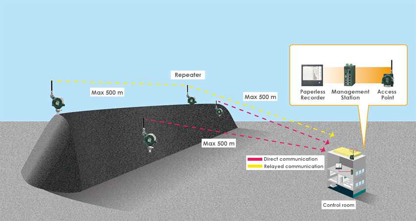
One important risk to manage with regard to coal stacks is preventing fires due to spontaneous combustion.

Yokogawa's Paperless Recorder series offers a multi-point touch panel to improve intuitive operator control with predictive monitoring for early detection during sake production and managing brewery wastewater.

Yokogawa’s Touchscreen GX10 Paperless Recorder eliminates the cost and labor associated with paper-based data recording.

Accurate and reliable data acquisition of temperature is critical in the processing of fresh milk.

As water and wastewater systems expand, scalable centralized monitoring enables efficient management of distributed assets and meets evolving user demands.


The SMARTDAC+ GX Series monitor furnace temperature in tunnel kiln furnaces and the like using Faceplate and Trend screens that come as standard features.

This recorder can efficiently control the heat treatment process, which is a critical control point (CCP) of HACCP, a hygiene management method in the food production process . It measures and records F values and elapsed time in the sterilization process of food and pharmaceuticals.
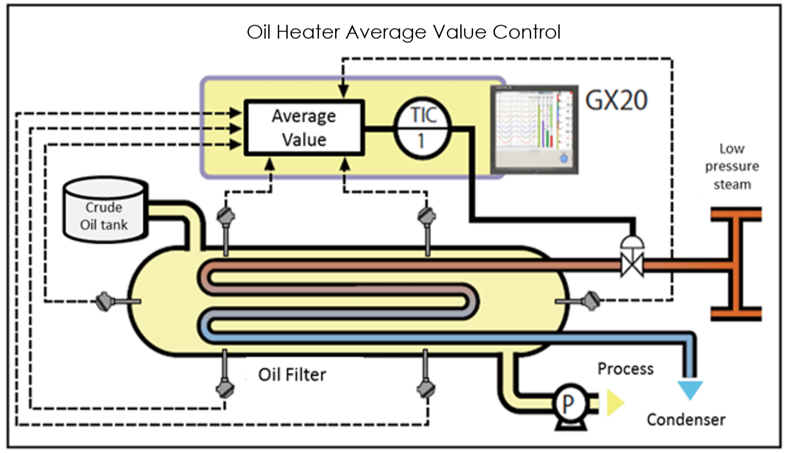
The GX20 and GX90UT offer an average value computation function making it ideal for controlling temperature and other fluctuating phenomena. The operating status can be controlled in real time, providing operating cost reductions.
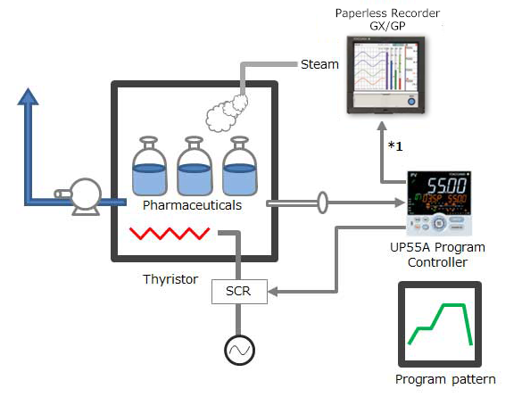
Performing control while changing the set point temperature moment by moment is called running a program pattern (or simply running a program). Sterilization and pasteurization require maintaining specific temperatures for specific durations.

The SMARTDAC+ GX is an ideal instrument for program control of a vacuum heat treatment furnace, and recording of subsequent data. A screen is available for monitoring of the program status.

Pressure measurement of tubeless tyres to monitor the air loss is one of the key performance tests in the tyre manufacturing units. Relocation of tyres from one testing rack to the other for various tests and frequent movement of the testing setup for conditional tests to various locations calls for cable free implementation for ease of handling.

AN 04L51B01-01EN

AN 04L51B01-02EN

The SMARTDAC+ recorder monitors wind direction and speed on-site or remotely, and sends instant email notifications if wind speed exceeds a specified threshold. This not only helps ensure safe loading and unloading of cargo at ports, but also prepares for natural disasters.

SMARTDAC+ GX series records the clean room temperature, humidity, atmospheric pressure, door openings and closings, etc.

AN 04L51B01-03EN

By using the Multibatch function (an option added with SMARTDAC+), you can efficiently record data from multiple devices onto a single SMARTDAC+.

The sterilization temperature prior to the filling process is monitored in the field or office. The temperature data is recorded in an external storage medium.

By using the computation function of the SMARTDAC+ series Paperless recorder GX/GP, computation option computes the "F-value," or sterilizing value for the sterilization process, so that the computation results can be recorded in the form of data.

- For remote monitoring (of temperature, pressure, and flow volume), installing the SMARTDAC+ GM in the plant and the SMARTDAC+ GX in the office provides for a scalable, pc-free on-site data monitoring solution.
- You can centralize management of large quantities of data by automatically transferring acquired data to a FTP server.

- Universal inputs provide support for thermocouple, RTD, voltage, and a variety of other input signals.
- Lineup of models for up to 450 inputs.
Allows multipoint monitoring and recording on a single unit. - Easily enables network-based data management.
file transfers, Web monitoring, and alarm e-mail


Read this eBook to learn how to best leverage the latest measurement instrumentation to avoid incidents and improve productivity. You will also find valuable information about overcoming common CIP challenges and stories of success.

Multi-touch technologies have rapidly moved from the commercial to the industrial sector where they are being used to enhance data analysis.

Why should leaders act on Digital Transformation, Autonomous Operations, and Smart Manufacturing? - Food Processing - eHandbook March 2022

Interview with Ryon Shaw, project engineer at the Michigan Milk Producers Association (MMPA), to get his perspective on the current state of digital recording in the dairy industry and his thoughts on the challenges facing facilities today.
Downloads
Brochures
- SMARTDAC+ Data Acquisition & Control Paperless Recorder GX/GP (9.8 MB)
- SMARTDAC+, the best-selling paperless recorder (data logger), now supports PROFINET! (1.3 MB)
- SMARTDAC+ Advanced Security Function Data Integrity Support for pharmaceutical & medical standards (1.3 MB)
- Yokogawa in the Food and Beverage Industry (5.9 MB)
- SMART 920 (4.0 MB)
- SMARTDAC+ series Easy connection to PROFINET devices (787 KB)
- Mining Solutions (3.2 MB)
- Yokogawa in the Pharmaceutical Industry (7.7 MB)
- Temperature Sensing Solutions (673.1 KB)
- SMART 920, 920 MHz band wireless communication instrument series (For US market only) (6.3 MB)
Instruction Manuals
- Precaution on the use of SMARTDAC+ (669.7 KB)
- Model GX10/GX20/GP10/GP20 Paperless Recorder First Step Guide (14.1 MB)
- Model GX10/GX20/GP10/GP20 Paperless Recorder User’s Manual (14.7 MB)
- Model GX10/GX20/GP10/GP20/GM10 Communication Command User's Manual (4.4 MB)
- Handling of the SD Memory Card (321 KB)
- Model GX10/GX20/GP10/GP20/GM10/GX90NW PROFINET Communication User's Manual (4.5 MB)
- SMARTDAC+ STANDARD Universal Viewer User's Manual (4.2 MB)
- Model GX10/GX20/GP10/GP20 Advanced Security Function (/AS) User’s Manual (4.7 MB)
- Cloud Equipment/Quality Predictive Detection Tool User’s Manual (166 KB)
- Model GX10/GX20/GP10/GP20/GM10 WT Communication (/E2) User’s Manual (1.5 MB)
- Regarding the Downloading and Installing for the Software, Manuals and Labels/About the Usage of Open Source Software (367 KB)
- Model GX10/GX20/GP10/GP20/GM10 EtherNet/IP Communication (/E1) User’s Manual (1.8 MB)
- Model GX10/GX20/GP10/GP20/GM10 Log Scale (/LG) User’s Manual (1011 KB)
- SMARTDAC+ STANDARD Hardware Configurator User's Manual (4.4 MB)
- Model 773230 Downloading the Validation Documents (132 KB)
- Model GX10/GX20/GP10/GP20/GM10 Multi-batch Function (/BT) User’s Manual (3.5 MB)
- Model GX10/GX20/GP10/GP20/GM10 OPC-UA Server (/E3) User’s Manual (884 KB)
- GX20/GP20 (/CM2 and /CM3 options), GM10 (/CM2, /CS2, /CM3 and /CS3 options) 920MHz wireless communication First Step Guide_US,KR (1.3 MB)
- Model GX10/GX20/GP10/GP20/GM10 SLMP Communication (/E4) User's Manual (2.1 MB)
- Model GX10/GX20/GP10/GP20/GM10 Loop Control Function, Program Control Function (/PG Option) User’s Manual (23.6 MB)
- Notes on using the Model GX90EX expansion module (I/O expansion module) (194 KB)
- DXA170 DAQStudio User's Manual (4.8 MB)
- Model GX20/GP20/GM10, UT52A/UT32A, UPM100 920 MHz Wireless Communication, MH920 Console International (For the US and the Korea) (12.0 MB)
General Specifications
- GX10/GX20 Paperless Recorder (Panel mount type) (3.9 MB)
- GX60 I/O Base Unit (Expandable I/O), GX90EX Expansion Module (3.1 MB)
- GX90XA/GX90XD/GX90YD/GX90WD/GX90XP/GX90YA I/O Modules (4.6 MB)
- GX90UT PID Control Module, GX10/GX20/GP10/GP20, GM, Loop Control Function, Program Control function (/PG) (1.8 MB)
- Equipment/Quality Predictive Detection Tool (340 KB)
- Model 773230 Validation Document for SMARTDAC+ (for the /AS option) (335 KB)
- 415940, 415941 and 415942 Shunt Resistor for Screw Input Terminal (178 KB)
- 438920, 438921 and 438922 Shunt Resistor for Clamp Input Terminal (252 KB)
- List of RoHS (2011/65/EU) Directive Compliant Products (6-substances RoHS compliant products) (356 KB)
- New Legislative Framework (NLF) Conforming Products (362 KB)
- GX20/GP20 (/CM2 option) GM (/CM2 and /CS2 options) 920MHz Wireless Communication (2.3 MB)
- List of the US Toxic Substances Control Act (TSCA) Compliant Recorder and Controller Products (175 KB)
Software
- Hardware Configurator *Log-in Required
- Universal Viewer *Log-in Required
- GA10 Data Logging Software *Log-in Required
- GA10 Data Logging Software [60-day free trial] *Log-in Required
- DAQStudio (DXA170) Revision Upgrade *Log-in Required
- Offline version: Equipment/Quality Predictive Detection tool OE10 *Log-in Required
- Validation Document for SMARTDAC+ *Log-in Required
- PLC Communication Protocol Profile (EDS file) for GX/GP (For connecting OMRON's PLCs) *Log-in Required
- SMARTDAC+ Report Template Builder *Log-in Required
- SMARTDAC+ Excel Report Simulator *Log-in Required
- SD Card Formatter *Log-in Required
- SMARTDAC+ SettingFileConverter Settings File Conversion Tool *Log-in Required
- GX/GP Firmware *Log-in Required
- Tag Plate *Log-in Required
- SMARTDAC+ I/O Module Firmware *Log-in Required
- EtherNet/IP Profile (EDS file) for GX/GP *Log-in Required
- SMARTDAC+ I/O Expansion Module Firmware *Log-in Required
- Mobile WEB Application for GX/GP/GM *Log-in Required
- LabVIEW Driver (for SMARTDAC+ Series) *Log-in Required
- SMARTDAC+ PID Control Module Fiemware *Log-in Required
- MH920 Wireless Communication module (Coordinator) Firmware *Log-in Required
Technical Information
- Effectively Using SMARTDAC+; Software Introduction (6.1 MB)
- SMARTDAC+ Advanced Security Functions White Paper for FDA 21 CFR Part 11 (587 KB)
- Reduce Risk by Eliminating Paper Chart Records (1.3 MB)
- GX/GP Custom Display Setup Guide (642 KB)
- Recorders, Data Loggers, and Control Products Security Standard (488 KB)
- DARWIN Replacement Guide (9.1 MB)
- High-speed Measurement Application High-speed Measurement/ Dual Interval Measurement Feature LR Replacement (8.9 MB)
- SMARTDAC+ Loop Control Function, Program Control Function (/PG Option) (9.5 MB)
- SMARTDAC+ CX Replacement Guide (Model and Suffix Code Replacement) (2.2 MB)
Engineering Tools
- Paperless Recorder GX10 (828 KB)
- Paperless Recorder GX20 (976 KB)
- Expandable I/O GX60 (575 KB)
- Expansion Module GX90EX (207 KB)
- PID Control Module GX90UT (219 KB)
- Digital Input/Output Module GX90WD (229 KB)
- Analog Input Module GX90XA (531 KB)
- Digital Input Module GX90XD (378 KB)
- Pulse Input Module GX90XP (329 KB)
- Analog Output Module GX90YA (265 KB)
- Digital Output Module GX90YD (267 KB)
Videos

Smart user interface, smart architecture, and smart functionality is achieved in the new Yokogawa SMARTDAC+ data acquisition and control product series. The Yokogawa SMARTDAC+ GX and GP are fully integrated measurement, display, and recording platforms equipped with an advanced touch screen operator interface. GX series is a panel-mount design, capable of operating in harsh industrial applications and environments. GP is the portable version of the GX, intended for use in lab and test bench applications.


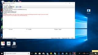


Join Data Acquisition Product Specialist Michael Stevenson as he guides you through GX20 to MW100 Modbus TCP setup.
This short video introduces SMARTDAC+ GX20 Data Acquisition Station and demonstrates how quickly we can set the unit up to do measurement and data recording.
This short video shows the method of adding input/output modules to the Yokogawa SMARTDAC+ Data Acquisition recording system and how to confirm correct installation.
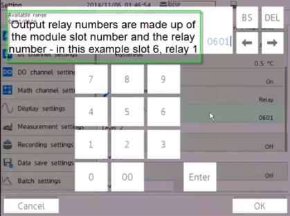
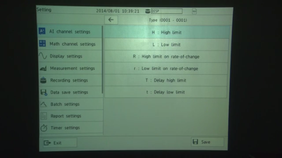
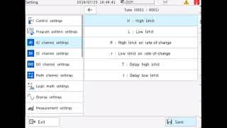
This short video shows the method of configuring alarms on the SMARTDAC+ paperless recorder. In this example setting a high alarm on channel 1 at 25 Deg C.

This short video shows the method of configuring group settings in SMARTDAC+ paperless recorder.
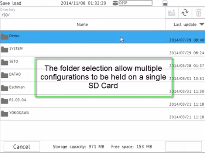
This short video shows the method of loading a configuration file stored on an SD card into a SMARTDAC+ paperless recorder.

This short video shows the method of configuring tag numbers in the SMARTDAC+ paperless recorder.
This video shows the capability of viewing information from the 21 CFR Part 11 compliant SMARTDAC+ paparless recorder range on an iOS or Android device


In this webinar, we will:
- Share best practices for monitoring, recording, and transferring data
- Challenges in data acquisition and how Yokogawa can help
- Demonstrate GA10 Data Logging Software capabilities

In this webinar, we will:
- Introduce Yokogawa AI, including Sushi Sensors
- Demonstrate GA10 AI Dashboard and simple setup
- Discuss applications and real-world examples
News
-
Press Release | Solutions & Products Jul 5, 2018 Yokogawa adds high-voltage analog input module to OpreX™ Data Acquisition lineup
Yokogawa adds high-voltage analog input module to OpreX™ Data Acquisition lineup.
-
Press Release Oct 30, 2012 New Yokogawa SMARTDAC+ Data Acquisition Station
Looking for more information on our people, technology and solutions?
Contact Us