Frequently Asked Questions: Lag Time Simplified
Q1. Is there is any correlation between lag time and process gas chromatograph (PGC or GC) cycle time?
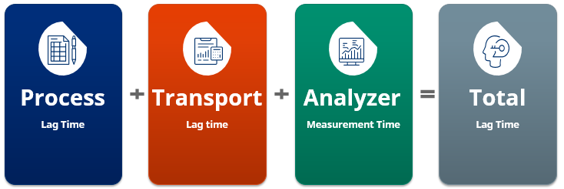
Answer: Sample transport time is calculated separately from the GC cycle time. The transport time and cycle time are added together to provide total lag time.
Q2. How does the process stream specification or application impact the lag time?
Answer: It depends on the application. The stream specification impacts issues such as the dew point of the sample, compatibility with metals/elastomers, and sample phase. Pressure and temperature are critical in calculating lag time as well as the sample return pressure.
Q3. For measurement of any particular gas, do we need to provide dry components or wet gas composition?
Answer: It depends on the analyzer technology being used for the desired end goal measurement. For example, a GC is always a wet analysis. It takes 100% of the sample and injects it into the analyzer, whereas a continuous emission monitoring system (CEMS) measurement is a dry measurement.
Q4. Does lag time have a major impact on SHS cost and functionality?
Answer: To an extent, the faster the lag time, the more expensive the components such as flowmeters will be. Also, the faster flow rate for faster lag times means more product flows through the fast loop, and depending on where this fast loop flow is returned can result in additional costs. An example is a flare return where the fast loop flow is burned in the flare.
Q5. What are the prerequisites to running the lag time calculation? Can we do it at the time of bidding or is it a part of the engineering activities?
Answer: It should be considered at the time of the engineering. During the bidding, a rough estimate lag time will be conducted based on the specification of process data, temperature, and given pressures.
Q6. Are there any quick reference lag time calculation excel sheets?
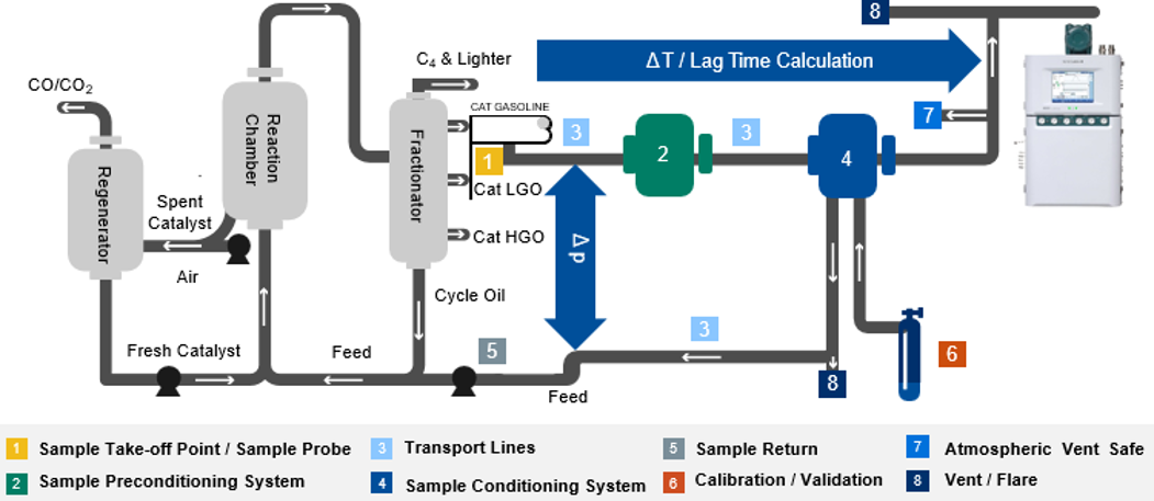
Answer: There are not, but the calculation overview is as follows:
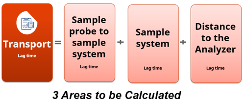
Remember when calculating the transport time, there are actually three areas to consider:
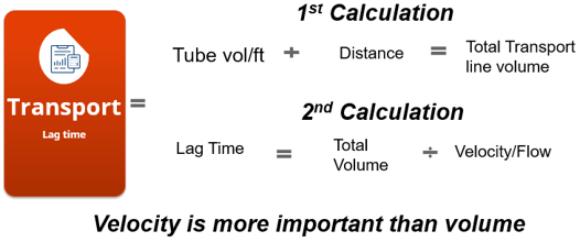
Q7. How do you calculate lag time?
Answer: Below are the calculations that must be considered.
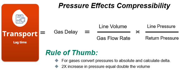
But do not forget the effect of pressure and the compressibility of the gases.
Q8. How do you calculate velocity and flow?
Answer: Based on lag time requirements, the bypass rotameter on the fast loop line can be sized to measure the flow rates.
Q9. How do you measure the pressure of the line? Transmitters or gauges?
Answer: Typically, gauges are used, but either is suitable.
Q10. How do you perform lag time across a vacuum diaphragm pump located on the SHS?
Answer: This is a difficult question to answer without a more detailed drawing or process diagram. The best practice would be to have a one on one detailed discussion with your local Yokogawa system integrator.
Q11. How do you compute the lag time of a stream with a vaporizer close to the sample point where the upstream fluid is liquid and the downstream fluid is vapor phase?
Answer: Separate the areas and think of them as two separate lag time calculations. The first would be from the sample point to the vaporizer, calculated as a liquid lag time. Then run the calculation again from the vaporizer to the SHS. The only other part that will need to be calculated is at the transition point. If the expansion ratio of the liquid to vapor can be calculated, the lag time of the short liquid tube can be calculated, as well.
NOTE: It is imperative to keep the vaporizer as close to the sample point tap as possible.
Q12. If we have fast loop tubes going back to the process and the analyzer outlet goes to atmosphere, which pressure shall we consider as return pressure in the calculation?
Answer: Two separate calculations are being asked about in this one question. There is a fast loop calculation and an analyzer calculation.
If the question is about the return from the sample valve, that would normally be returned online beyond the rotameter. However, the analyzer vent would be determined by the sample mixture and where it can be returned to meet local regulatory compliance. That is something that can provide a steady pressure such as atmosphere. That way, it can be sent to a catalytic converter/trace eraser).
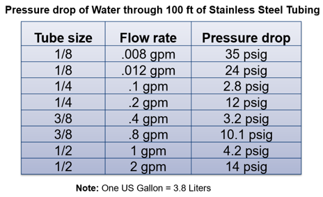
Q13. If we are going to use a similar size of sample transport tube, how dependent is the lag time on the type of sample transport tube being used (i.e. using a pipe, seamless tube, or an internal polished tube)?
Answer: There are commonly known reference data available. Below are just some quick examples.
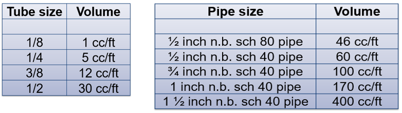
But don’t forget about drop reference values.

Q14. Will the time required for any pressure changes at the probe end be reflected at the GC? Will they be the same as the lag time?
Answer: It will affect the lag time. If there is a process pressure change and a regulator is not being used, then the pressure change will be the delta between the supply and the return. As those become closer to equal it will lose flow, and any changes will affect the lag time.
This frequently happens when sample returns are on the downstream side of a control valve that is constantly changing. Another example is when the sample flares and the flare changes constantly.
Q15. What is the possibility of surging/back pressure from the process line? For example, we design the SHS for the analyzer and want the discharge or vent line connected to the process again?
Answer: Return pressure should be somewhat stable for best operation but a check valve should be installed in the sample return line to protect the SHS during upset conditions.
Related Products & Solutions
-
GC1000 Mark II
The ability to perform discrete separation and positive identification of components and measurement of the composition without interference is an advantage of the gas chromatograph. The process gas chromatograph is widely used in many industries.
-
Gas Analyzers
Enhance efficiency and product quality with real-time analysis
-
Process Gas Chromatograph GC8000
Streamline plant operations with user friendly interfaces
-
Process Gas Chromatographs
Streamline analysis and maintenance