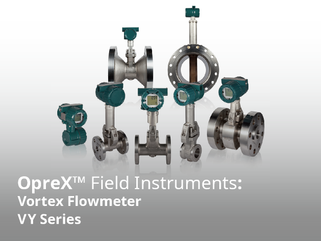


Yokogawa's Vortex Flowmeters VY Series is developed with two key technologies, the digital technology and inherited unique structure from YEWFLO series.
Digital technology is utilized to enable remote maintenance and self-diagnosis, to easily check the health of your equipment at any time. The unique structure provides robustness and long-term stable measurement.
VY series supports various standards such as SIL2, local Ex proof.
It has various calculation functions such as temperature pressure compensation and energy calculation.
VY series contributes to the efficient and planned operation of the customer plant.
About OpreX
OpreX is the comprehensive brand for Yokogawa’s industrial automation (IA) and control business and stands for excellence in the related technology and solutions. It consists of categories and families under each category. This product belongs to the OpreX Field Instruments family that is aligned under the OpreX Measurement category.
Details
VY Series Overview
Digitalization
Supporting Efficient and Planned Plant Operations
In a plant where a large number of equipment is in operation, efficient and systematic maintenance activities are required according to the equipment condition.
The VY series equip with complete device self-diagnosis function including the shedder bar and sensor elements by further advanced the digitalization of internal signals. This improves reliability, including for safety instrumentation loops (complies with SIL2). The remote maintenance function allows easily checking the health of the equipment from the computer in the instrument room without the need to go to the site. Yokogawa's vortex flowmeter has been well-established as maintenance-free. With enhanced self-diagnosis and remote maintenance functions, it realize condition-based maintenance of the vortex flowmeter.


Inheritance
Stable Measurement and High Maintainability
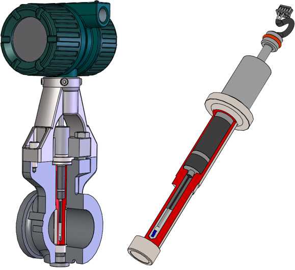
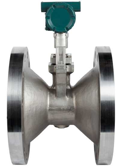
The VY series inherits the reliable and proven detection structure unique to the YEWFLO series.
It is the only removable vortex shedder bar with two flow sensors and one built-in temperature sensor. This structure brings robustness, long-term stability, short face-to-face length, and shortened upstream straight pipe length.
Even if maintenance is required, eg. due to process upset, there is no need to remove the entire flowmeter from the pipe. Partial cleaning and replacement of the vortex shedder bar is possible. In addition, by performing digital signal processing with a unique structure equipped with two sensor elements, pipe vibration is eliminated effectively.
Since the unique detection structure and face-to-face length are compatible with the previous YEWFLO series, VY series can be installed in the same place without additional work for piping.
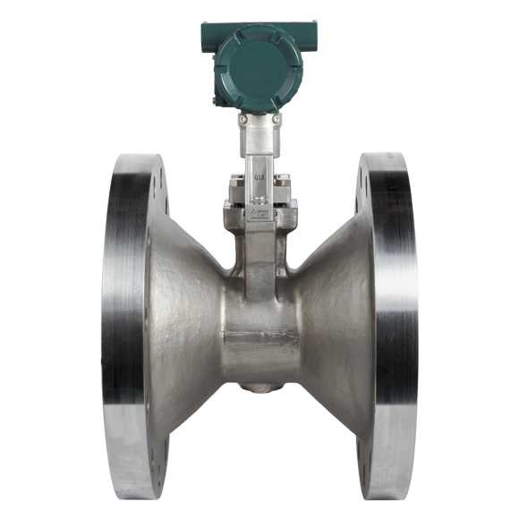
General Type
This type is the basic type of the VY series.
This model can measure the flow rate of liquids, gas and steam. We have a lineup of sizes up to 400 mm. The process temperature range is from -40 ℃ to +250 ℃, and the process pressure range is up to ASME Class900. The material of the wetted part is made of stainless steel or nickel alloy. It also complies with wide regulations such as explosion protection and SIL2.
The analog input function (HART7, when analog input specification is selected) is used to support the calculation function* such as mass flow rate and energy flow rate of liquid, gas and steam.
The VY series used digital technology to achieve self-diagnosis and remote maintenance.
*: It has a built-in saturated, and superheated steam table

[Common Specification]
| Model | VY □ □ □ (Integral Flowmeter, Remote Sensor), VY4A (Remote Transmitter) |
|---|---|
| Measurement Fluid | Liquid, Gas, Saturated Steam, Superheated Steam (Avoid multiphase flow and sticky or corrosive fluids) |
| Communication and Input/Output | HART 7 communication, 4 to 20 mA DC, Pulse / Status output, Analog input |
| Explosion Protected Type | IECEx Ex db / Ex ia, ATEX Ex db / Ex ia, FM Ex db / Ex ia, FMc Ex db / Ex ia, Japan Ex db, NEPSI Ex db / Ex ia, Korea Ex db / Ex ia |
| Conformity Standards | EMC, PED, EU RoHS, CE marking, NACE, Functional Safety (SIL2), NAMUR (NE21 / NE107), Marine Certificate (ABS, DNV) |
[Specific Specification of General Type]
| Type of Body | General Type | |
|---|---|---|
| Type of Shedder Bar | General Type, Long Neck Type | |
| Accuracy | ±0.75 % of reading (liquid), ±1 % of reading (gas, steam) | |
| Process Temperature | -40 °C to 250 °C | |
| Max Process Pressure | ASME Class 900, EN PN40, JIS 40K | |
| Ambient Temperature | -40 ( / -50 ) °C to 85 °C | |
| Connection Size | Wafer | From 15 to 100 mm |
| Flange | From 15 to 400 mm | |
| Degree of Protection | IP66 / IP67 | |
Refer to the General Specification sheet located under the Downloads tab for detailed specifications.
Built-in Temperature Sensor Type
This type is a flowmeter with a built-in temperature sensor (Pt1000) in the shedder bar (vortex generator), and can measure the process fluid temperature at the same time.
Size is from 25 mm to 300 mm. It can be combined with the High Temperature Type and Reduced Bore Type. It covers a wide range of fluid measurement.
The measured temperature can be used for temperature compensation. In addition, combination with analog input signal (eg. pressure...) supports more accurate flow measurement.
[Specific Specification of Built-in Temperature Sensor Type]
| Type of Body | General Type [Combinationable Body] Reduced Bore Type (1 or 2 size reduction) |
|
|---|---|---|
| Type of Shedder Bar | General Type with Temperature Sensor, Long Neck Type with Temperature Sensor [Combinationable Shedder bar] Hight Temperature Type with Temperature Sensor |
|
| Accuracy | ±0.75 % of reading (liquid), ±1 % of reading (gas, steam) | |
| Process Temperature | -40 °C to 250 °C | |
| Max Process Pressure | ASME Class 900, EN PN40, JIS 40K | |
| Ambient Temperature | -40 ( / -50 ) °C to 85 °C | |
| Connection Size | Wafer | From 25 to 100 mm |
| Flange | From 25 to 300 mm | |
| Degree of Protection | IP66 / IP67 | |
Refer to the General Specification sheet located under the Downloads tab for detailed specifications.
High Temperature / Cryogenic Type
These types use materials and sensors required for high temperature / cryogenic environment.
Size of High temperature type is from 25 mm to 400 mm, it can be measured high temperature fluid up to +450 ℃ (up to +400 ℃ with a built-in temperature sensor type).
Size of Cryogenic type is from 15 mm to 100 mm, it can be measured cryogenic temperature fluid up to -196 ℃.
It is possible to select either type as an integral type or remote type.

[Specific Specification of High Temperature Type]
| Type of Body | General Type [Combinationable Body] Reduced Bore Type (1 or 2 size reduction) |
|
|---|---|---|
| Type of Shedder Bar | High Temperature Type High Temperature Type with Temperature Sensor |
|
| Accuracy | ±0.75 % of reading (liquid), ±1 % of reading (gas, steam) | |
| Process Temperature | -40 °C to 450 °C | |
| Max Process Pressure | ASME Class 900, EN PN40, JIS 40K | |
| Ambient Temperature | -40 ( / -50 ) °C to 85 °C | |
| Connection Size | Wafer | From 25 to 100 mm |
| Flange | From 25 to 400 mm | |
| Degree of Protection | IP66 / IP67 | |
[Specific Specification of Cryogenic Type]
| Type of Body | General Type [Combinationable Body] Reduced Bore Type (1 or 2 size reduction) |
|
|---|---|---|
| Type of Shedder Bar | Cryogenic Type | |
| Accuracy | ±0.75 % of reading (liquid), ±1 % of reading (gas, steam) | |
| Process Temperature | -196 °C to 250 °C | |
| Max Process Pressure | ASME Class 900, EN PN40, JIS 40K | |
| Ambient Temperature | -40 °C to 85 °C | |
| Connection Size | Wafer | From 15 to 100 mm |
| Flange | From 15 to 100 mm | |
| Degree of Protection | IP66 / IP67 | |
Refer to the General Specification sheet located under the Downloads tab for detailed specifications.
Reduced Bore Type (1 or 2 Size Reduction)
This type has a structure in which both the upstream and downstream sides of the sensor are integrated with the reducer (reduced pipe and expansion pipe). It is suitable for easy replacement of lines with large flow rate fluctuation depending on the season.
There are two types of reduced bore type, one size reduction and two size reduction, and the size is up to 200 mm with flange type. It can be combined with built-in temperature sensor type and high temperature / cryogenic type, and can be used for a wide range of fluid measurements.
[Specific Specification of Reduced Bore Type (1 or 2 Size Reduction)]
| Type of Body | Reduced Bore Type (1 or 2 size reduction) | |
|---|---|---|
| Type of Shedder Bar | General Type [Combinationable Shedder bar] General Type with Temperature Sensor, High Temperature Type High Temperature Type with Temperature Sensor, Cryogenic Type |
|
| Accuracy | ±1.0 % of reading (liquid), ±1.5 % of reading (gas, steam) | |
| Process Temperature | -40 °C to 250 °C | |
| Max Process Pressure | ASME Class 300, JIS 20K | |
| Ambient Temperature | -40 ( / -50 ) °C to 85 °C | |
| Connection Size | ||
| Flange | 1 size reduction: 25 to 200 mm 2 size reduction: 40 to 200 mm |
|
| Degree of Protection | IP66 / IP67 | |
Refer to the General Specification sheet located under the Downloads tab for detailed specifications.
High Pressure Type
This type is one size reduction type that has a flange pressure rating with ASME Class 1500. The sturdy structure enables stable measurement even in the harsh environment of high pressure.
Size is from 25 mm to 150 mm in combination with general type sensor.

[Specific Specification of High Pressure Type]
| Type of Body | High Pressure Reduced Bore Type ( 1 size reduction) | |
|---|---|---|
| Type of Shedder Bar | General Type | |
| Accuracy | ±0.75 % of reading (liquid), ±1 % of reading (gas, steam) | |
| Process Temperature | -40 °C to 250 °C | |
| Max Process Pressure | ASME Class 1500 | |
| Ambient Temperature | -40 ( / -50 ) °C to 85 °C | |
| Connection Size | ||
| Flange | 25 to 150 mm | |
| Degree of Protection | IP66 / IP67 | |
Refer to the General Specification sheet located under the Downloads tab for detailed specifications.
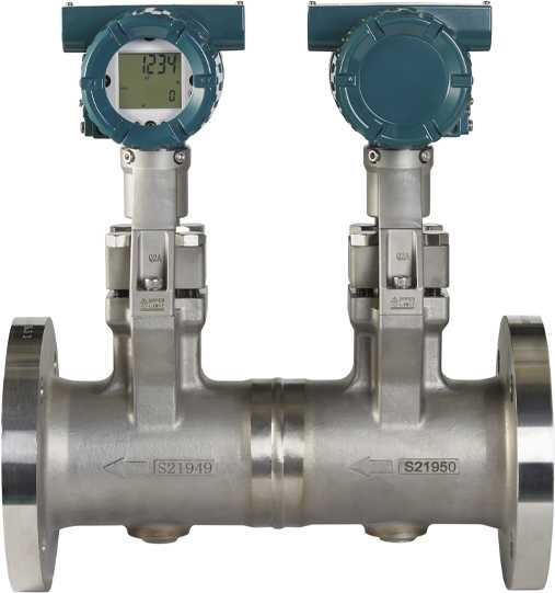
Dual-Sensor Type
This type is dual-sensor (welded) type that has a flange pressure rating with up to ASME Class 900. The structure of these two units connected in series is the best choice for applications requiring high reliability.
Size is from 15 mm to 200 mm in combination with several type sensor.
[Specific Specification of Dual-Sensor Type]
| Type of Body | Dual-Sensor (Welded) General Type | |
|---|---|---|
| Type of Shedder Bar* | General Type, Long Neck Type [Combinationable Shedder bar] General Type with temperature sensor, Long Neck Type with temperature sensor, High Temperature Type, High Temperature Type with temperature sensor, Cryogenic Type |
|
| Accuracy | ±0.75 % of reading (liquid), ±1 % of reading (gas, steam) | |
| Process Temperature | -196 °C to 450 °C | |
| Max Process Pressure | ASME Class 900 | |
| Ambient Temperature | -40 ( / -50 ) °C to 85 °C | |
| Connection Size | ||
| Flange | 15 to 200 mm | |
| Degree of Protection | IP66 / IP67 | |
* Type of shedder bar is same as upstream and downstream
* Refer to the General Specification sheet located under the Downloads tab for detailed specifications.
Total Insight - Overview-
From Sensing to Sensemaking

Total Insight is the product concept to support customers every phase of the product lifecycle. VY series has developed based on Total Insight concept.
Yokogawa reviewed the overall lifecycle related to operations and costs, and formulated a design concept with the aim of solving the problems at hand. And aim to reduce operating costs throughout that life cycle.
- Simplified Selection : Reduce engineering hours and procurement costs
- Smart Assist : Reduction of operation start-up time
- Process Guard : Increase operational efficiency and reduce errors
- Expert Solution : Improving maintenance work efficiency
Total Insight - Simplified Selection -

Truly Universal Lineup
Model Selection Is Easy
- Provides specification selection tools including sizing
- A wide flow range up to size 400 mm is available. And the Reduced Bore Type can be supported by two sizes down.

- The face to face lengths are the same as those of the previous YEWFLO series, so it can be used for a long time.

Supports a Wide Range of Standards
- Functional Safety IEC 61508 compliant Safety Integrity Level SIL2
- Explosion protection: IECEx, ATEX, FM, FMc, Japan, Taiwan, UAE
- General Safety, EMC, PED, EURoHS, CE Mark, CRN, ABS / DNV ship's classification
- Industry standards: NAMUR NE21 , NE107, NACE materials
Built-in Abundant Calculation Function
- Calculates volume, mass and energy flow rates using temperature / pressure / density from the built-in tenperature sensor or current input
- Calculates mass and energy of saturated / superheated steam using the built-in steam table

Total Insight - Smart Assist -

Vibration-Resistant and Stable Flow Measurement
Realizes Stable Measurements
- Yokogawa's unique structure which are integrated the sensor and the shedder bar, captures vortex signals with the entire shedder bar
- Provides stable measurement even with short straight pipe lengths, regardless of the installation orientation

Accurately Captures Flow Signals
- Unique structure with two sensor elements cancels piping vibration noise
- Mature and proprietary digital signal processing technology (SSP*) eliminates noise and extracts vortex signals only
- Alarm outputs possible false outputs due to piping vibration

* SSP: Yokogawa's proprietary signal processing that removes noise extracts vortex signals from two sensor elements.
Ready to Use Right After Installation
- Parameters are factory-set before shipment
- Automatic adjustment function of SSP makes field adjustment omitted
- Verification tools including Waveform monitoring facilitate post-installation condition checks
Total Insight - Process Guard -

Advanced Self-Diagnostics and Remote Maintenance
Ready to Diagnose All Function Blocks
- All functional blocks are self-diagnosed in compliance with the requirements of the SIL2 standard for functional safety
- Easily identifies where device maintenance is required

Confirms Device Health From Remote Locations Such as Instrument Room
- Wizard style remote maintenance with FSA130 Verification Tool
- Check vortex signal waveforms from the instrument room without bringing an oscilloscope to the site
Supports Condition-Based Maintenance
- FSA130 Verification Tool can predict sensor status
Total Insight - Expert Solution -

Smart Device Maintenance
Easy to Identify Process-Side or Device-Side Abnormality
- Process diagnostics detect piping vibration and fluid fluctuations
- Self-diagnostic function monitors device health

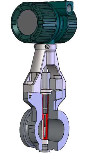
Unique Shedder Bar Structure
- Yokogawa's unique shedder bar structure is known for its robustness and long-term stability
- The shedder bar can be removed for cleaning or replacement in case of unforeseen circumstances
Reduced Downtime
- The parameters of the transmitter can be backed up to the sensor and it is easy to restore when replacing the transmitter

Technical Information - Measurement Principle -
Vortex Flow Meters - Principle of Operation
Vortex Flow Meters use the Von Karman Effect to measure the rate of flow of a fluid or gas.
What Is the Von Karman Effect?
Early in the 20th century, a Hungarian-American mathematician and physicist, Theodore von Karman, discovered that a fluid or gas flowing perpendicularly pass a bluff body would generate alternating vortices on both sides of the body. The path of these vortices is called the von Karman vortex street.

Von Karman found that if the frequency of these vortices was measured, that the frequency is proportional to the flow velocity that is generating the vortices. This frequency is called the Karmen Vortex Frequency. The relationship of the frequency and the flow velocity can be mathematically expressed with the following formula:
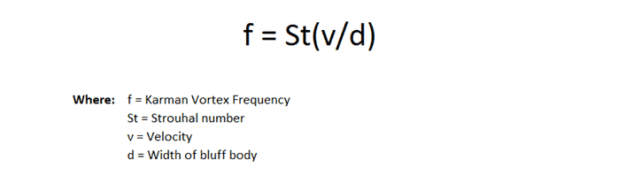
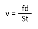
From the equation, we can see that the frequency is proportional to the velocity. If we can measure the frequency (f), know the Strouhal number (St), know the shedder bar width (d); we can solve for v (velocity).
How Do We Measure the Frequency of the Vortices?
As vortices form and pass the shedder bar (the bluff body), they create a low pressure as compared to the rest of the fluid. This low pressure produces a differential pressure (dp) across the shedder bar. The high pressure side of the dp exerts stress on the shedder bar in the direction of the low pressure. As the location of the low pressure side alternates due to the vortices switching from side-to-side, the change in direction of the exerted force causes the shedder bar to oscillate. This oscillation is equal to the Karmen Vortex Frequency.

There are several methods in the marketplace to measure the oscillation. Diaphragms or capacitance sensors are two of the more common; but, the best method is the use of Piezo-electric crystal sensors. These sensors, when compressed, produce an electric signal that can be sent to the Flow meter's electronics. Now that the Karmen Vortex Frequency is measured (and we know the St and d), the flow meter electronics can do simple calculations to determine volumetric flow through the pipe.
What Are the Advantages of Using Vortex Flow Meters?
- High Accuracy
The accuracy of the vortex flow meter is ±1% (pulse output) of the indicated value for both liquids and gases and is higher compared to orifice flow meters. For liquids, an accuracy of ±0.75% is available depending on the fluid type and their conditions. - Wide Rangeability
Rangeability is defined as the ratio of maximum value to minimum value of the measurable range. It is broad rangeability the allows vortex flow meters to operate in processes where the measuring point may fluctuate greatly. - Output Is Proportional to Flow Rate
Since the output is directly proportional to the flow rate (flow velocity), no square root calculation is needed, while orifice flow meters require square root calculations. - No Zero-point Fluctuation
Since frequency is output from the sensor, zero-point shift does not occur. - Minimal Pressure Loss
Since only the vortex shedder is placed in the pipe of the vortex flow meter, the fluid pressure loss due to the small restriction in the flow piping is small compared with flow meter a having an orifice plate.
Combining Noise Reduction and Spectral Signal Processing (SSP) to provide an accurate and stable measurement.
Technical Information - Sensing Technology -
Signal Processing (SSP: Spectral Signal Processing)
VY series's SSP Function Provides Enhanced Vibration Immunity and Advanced Diagnostics
VY series is a maintenance-free flowmeter. It has a circuit for analyzing the frequency of detected signal and allows only vortex frequency to pass through the segmented band-pass-filter, thereby accurately identifying and eliminating noise. The Spectral Signal Processing (SSP) function of VY series only outputs the appropriate vortex frequencies, even under fluctuating flow rate conditions.

Noise Reduction
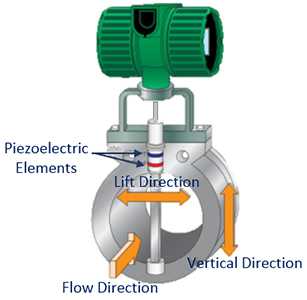
Noise caused by strong piping vibration may affect the accuracy of the vortex frequency detection. The two piezoelectric elements installed in the VY series are of a polarized structure, so they do not detect vibration in the flow or vertical directions. The noise in the lift direction vibration is reduced by adjusting the outputs of the piezoelectric elements.
Technical Information - Straight Pipe Length -
Straight Pipe Length According to Installation Situation
Vortex flowmeters generally affect flow measurement accuracy when the flow velocity distribution in the pipe is biased.
Necessary straight pipe length and main points are shown along with typical installation examples.
Straight Pipe
Secure at least 10D upstream and 5D downstream.

Reducer Pipe
Secure at least 5D upstream and 5D downstream.

Expander Pipe
Secure at least 10D upstream and 5D downstream.

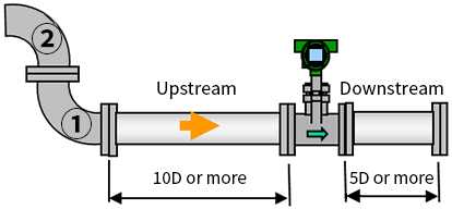
Single Bent Pipe
Secure at least 10D upstream and 5D downstream.

Double Bent Pipe in the Same Plane
Secure at least 10D upstream and 5D downstream.
Double Bent Pipe in Another Plane
Secure at least 20D upstream and 5D downstream.

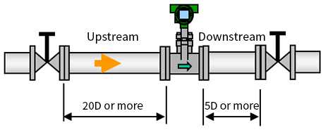
Valve Position and Straight Pipe Length
Install the valve on the downstream side of the flowmeter. The upstream straight pipe length dependent on the element located on the upstream such as reducer/expander, bent and etc., refer to description as above. Keep 5D or more for downstream straight pipe length.
In case the valve has to be installed on the upstream of the flowmeter, ensure the upstream straight pipe length to be 20D or more, and the downstream straight pipe length be 5D or more.
Technical Information - Mounting Attitude -
If the pipe is always filled with fluid, the mounting direction does not matter whether it is horizontal, vertical or inclined.
However, in the case of horizontal and inclined, be sure to install the terminal box or converter above the piping position in order to avoid flooding.
Horizontal Piping


Vertical Piping


Inclined Piping


Resources

In steam-driven processes, the mass flow rate is a key performance indicator. Without accurate mass flow data, operators risk inefficient fuel use, inaccurate energy balancing, and unstable boiler control. A high-precision, compact vortex flowmeter with built-in temperature sensing helps deliver real-time, reliable mass flow measurement, reducing costs and improving operational efficiency.

Accurate Steam Measurement from Start-up to Full Operation; Steam flow varies widely from start-up to full load. This note highlights how multivariable vortex technology ensures accurate, reliable measurement across all conditions.

Optimizing Steam Injection for Enhanced Oil Recovery with Vortex VY Flowmeter Series. Steam injection is one of the most effective enhanced oil recovery (EOR) methods, but harsh operating conditions demand reliable, maintenance-free flow measurement solutions.

The key to achieving stable and safe plant operation and overall optimization is to improve the efficiency and labor saving of device maintenance. Vortex Flowmeters VY Series can support these by the digitalization technology to improve the efficiency of maintenance work and the unique sensing structure with excellent maintainability.

This article concisely explains measurement principles of vortex flowmeters and the objects they measure.

Unbalanced velocity distribution and fluid turbulence in a pipe disturb Karman Vortices and affect the accuracy of flow measurement. Therefore, straight pipe lengths are needed. This article shows the reasons why straight pipe lengths are necessary, using flow simulation and VY Series Vortex Flowmeters as examples.
View TechStar Blog
Downloads
Brochures
Instruction Manuals
- Vortex Flowmeter VY Series Read Me First (1.1 MB)
- Vortex Flowmeter VY Series Installation Manual (5.4 MB)
- Vortex Flowmeter VY Series Safety Manual (345 KB)
- Vortex Flowmeter VY Series Maintenance Manual (2.6 MB)
- Vortex Flowmeter VY Series HART Communication Type (2.6 MB)
- Vortex Flowmeter VY Series FOUNDATION Fieldbus Communication Type (3.9 MB)
- Vortex Flowmeter VY Series Modbus Communication Type (3.1 MB)
- Vortex Flowmeter VY Series FM (USA) Explosion Protection Type (581 KB)
- Vortex Flowmeter VY Series FM (Canada) Explosion Protection Type (580 KB)
- Vortex Flowmeter VY Series ATEX Explosion Protection Type (916 KB)
- Vortex Flowmeter VY Series IECEx Explosion Protection Type (965 KB)
- Vortex Flowmeter VY Series Verification Tool (41.5 MB)
- Vortex Flowmeter VY Series INMETRO Explosion Protection Type (995 KB)
General Specifications
Technical Information
- Vortex Flowmeter VY Series (1.5 MB)
- FMEDA YEWFLO TI YEC 21-01-069 R002 V2R1 (626.3 KB)
- FMEDA YEWFLO TI YEC 20-04-072 R001 V2R2 (0.9 MB)
Certificates
Engineering Tools
- Vortex Flowmeter VY Series, VY4A, Remote Transmitter (1.1 MB)
- Vortex Flowmeter VY Series, VY015, VY025, VY040, General Type Process, Connection: ASME Wafer (1.2 MB)
- Vortex Flowmeter VY Series, VY050, VY080, VY100, General Type, Process Connection: ASME Wafer (1.2 MB)
- Vortex Flowmeter VY Series, VY015, VY025, VY040, General Type, Process Connection: EN Wafer (1.2 MB)
- Vortex Flowmeter VY Series, VY050, VY080, VY100, General Type, Process Connection: EN Wafer (1.2 MB)
- Vortex Flowmeter VY Series, VY015, VY025, VY040, General Type, Process Connection: JIS Wafer (1.2 MB)
- Vortex Flowmeter VY Series, VY050, VY080, VY100, General Type, Process Connection: JIS Wafer (1.2 MB)
- Vortex Flowmeter VY Series, VY015, VY025, VY040, General Type, Process Connection: ASME Flange (1.2 MB)
- Vortex Flowmeter VY Series, VY050, VY080, VY100, General Type, Process Connection: ASME Flange (1.2 MB)
- Vortex Flowmeter VY Series, VY150, VY200, General Type, Process Connection: ASME Flange (1.2 MB)
- Vortex Flowmeter VY Series, VY250, VY300, VY400, General Type, Process Connection: ASME Flange (1.2 MB)
- Vortex Flowmeter VY Series, VY015, VY025, VY040, General Type, Process Connection: EN Flange (880 KB)
- Vortex Flowmeter VY Series, VY050, VY080, VY100, General Type, Process Connection: EN Flange (881 KB)
- Vortex Flowmeter VY Series, VY150, VY200, General Type, Process Connection: EN Flange (849 KB)
- Vortex Flowmeter VY Series, VY015, VY025, VY040, General Type, Process Connection: JIS Flange (1.2 MB)
- Vortex Flowmeter VY Series, VY150, VY200, General Type, Process Connection: JIS Flange (1.2 MB)
- Vortex Flowmeter VY Series, VY050, VY080, VY100, General Type, Process Connection: JIS Flange (1.2 MB)
- Vortex Flowmeter VY Series, VY250, VY300, VY400, General Type, Process Connection: JIS Flange (1.2 MB)
- Vortex Flowmeter VY Series, VY025, VY040, VY050, Reduced Bore Type (1 Size Reduction), Process Connection: ASME Flange (998 KB)
- Vortex Flowmeter VY Series, VY080, VY100, VY150, Reduced Bore Type (1 Size Reduction), Process Connection: ASME Flange (1.2 MB)
- Vortex Flowmeter VY Series, VY200, Reduced Bore Type (1 Size Reduction), Process Connection: ASME Flange (1.2 MB)
- Vortex Flowmeter VY Series VY025, VY040, VY050 Reduced Bore Type (1 Size Reduction) Process Connection: EN Flange (1021 KB)
- Vortex Flowmeter VY Series VY080, VY100, VY150 Reduced Bore Type (1 Size Reduction) Process Connection: EN Flange (874 KB)
- Vortex Flowmeter VY Series VY200 Reduced Bore Type (1 Size Reduction) Process Connection: EN Flange (839 KB)
- Vortex Flowmeter VY Series, VY025, VY040, VY050, Reduced Bore Type (1 Size Reduction), Process Connection: JIS Flange (998 KB)
- Vortex Flowmeter VY Series, VY080, VY100, VY150, Reduced Bore Type (1 Size Reduction), Process Connection: JIS Flange (1.2 MB)
- Vortex Flowmeter VY Series, VY200, Reduced Bore Type (1 Size Reduction), Process Connection: JIS Flange (1.2 MB)
- Vortex Flowmeter VY Series, VY040, VY050, VY080, Reduced Bore Type (2 Size Reduction), Process Connection: ASME Flange (993 KB)
- Vortex Flowmeter VY Series, VY100, VY150, VY200, Reduced Bore Type (2 Size Reduction), Process Connection: ASME Flange (1.2 MB)
- Vortex Flowmeter VY Series, VY040, VY050, VY080, Reduced Bore Type (2 Size Reduction), Process Connection: JIS Flange (993 KB)
- Vortex Flowmeter VY Series, VY100, VY150, VY200, Reduced Bore Type (2 Size Reduction), Process Connection: JIS Flange (1.2 MB)
- Vortex Flowmeter VY Series, VY025, VY040, VY050, High Pressure Reduced Bore Type (1 Size Reduction), Process Connection: ASME Fl (959 KB)
- Vortex Flowmeter VY Series, VY080, VY100, VY150, High Pressure Reduced Bore Type (1 Size), Process Connection: ASME Flange (959 KB)
- Vortex Flowmeter VY Series VY015 Dual-Sensor (Welded) General Type Process Connection: ASME Flange (1023 KB)
- Vortex Flowmeter VY Series VY025, VY040, VY050 Dual-Sensor (Welded) General Type Process Connection: ASME Flange (1.0 MB)
- Vortex Flowmeter VY Series VY080, VY100 Dual-Sensor (Welded) General Type Process Connection: ASME Flange (1022 KB)
- Vortex Flowmeter VY Series VY150, VY200 Dual-Sensor (Welded) General Type Process Connection: ASME Flange (995 KB)
- Vortex Flowmeter VY Series VY015 Dual-Sensor (Welded) General Type Process Connection: EN Flange (1022 KB)
- Vortex Flowmeter VY Series VY025, VY040, VY050 Dual-Sensor (Welded) General Type Process Connection: EN Flange (1022 KB)
- Vortex Flowmeter VY Series VY080, VY100 Dual-Sensor (Welded) General Type Process Connection: EN Flange (1021 KB)
- Vortex Flowmeter VY Series VY150, VY200 Dual-Sensor (Welded) General Type Process Connection: EN Flange (994 KB)
Videos

The self-diagnostic and remote maintenance functions support Condition Based Maintenance, which performs efficient and planned maintenance. Inherited YEWFLO's sensing structure brings robustness and long term stability.
Discover how Yokogawa’s Total Insight Flowmeters with Process Guard transform operational safety and efficiency. In this video, we highlight its advanced capabilities in monitoring, diagnostics, and proactive intervention to minimize risks and maximize uptime.

Our experts review the theory behind flow measurement technologies. Discuss common flow application challenges and evaluate the different technologies when selecting a flow meter. They also give examples of best installation practices for successful measurements.
2D/3D Configurator
Looking for more information on our people, technology and solutions?
Contact Us